Condition Report: Lead Marks in NV, Köln Dom
The report describes the condition of unusual leads noticed within the medieval lead matrix of NV, which have a pattern of repeated marks. 8 panels from the window have been examined for this report: 2AB11, 2AB12, 2AB13, 2AB15, 2B, 2CD6, 4BC9 and 10c3. The method of examination was visual, at close range on a workbench, using reflected light and a microscope. For the purpose of this report, ‘marks’ refer to repeated marks that appear over the length of the lead. Other kinds of marks such as air bubbles, scratches and dents are not the focus of this study and therefore are not considered.
The methodology of data collection is outlined first. Then brief condition reports for each panel included in the survey, focusing on the lead marks. These short reports include a mapping of the marks found on each panel; detail photography of all marks, and a brief overview of the observations made during examination. Any general observations noted during the course of visual examination are summarised in a final condition resorts summary, which includes an analysis of data collected during observations. This data is included in full in the appendix of the report.
Firstly the marks on the panel are mapped using vector software. Both the front and back are mapped and the marks are then transferred into one composite image. Colour-coding is used to clarify which mark is on which side, as well as easily identify leads marked on both sides. This mapping allows for each marked lead to be given an identifying number working from bottom to top, left to right, mirroring the CVMA panel numbering system. This number is combined with a panel identifier to create a unique ID for each lead discussed in this report. Marks are additionally identified by adding an ‘i’ or ‘o’ to indicate whether they are found on the lead’s inside or outside. In one case where two very different marks were found on one lead, these were distinguished by adding ‘a’ or ‘b’ to the end of the mark ID.
Next data on each mark is collected. Data collected includes the following categories.
Panel ID | The standard numbering used in the Dombauhütte. |
Lead ID | A unique identifier for each marked lead. |
Mark ID | A unique identifier for each mark. |
Outside/ Inside | Which side of the panel the mark is found |
Lead Profile | What does the shape of the lead look like in profile? |
Lead width | The width of the lead in millimetres. |
Mark Length | The length of the mark in millimetres. |
Mark Shape | What does the mark look like, is it a recognizable shape? |
Mark Frequency | Recorded as the average distance between marks in millimetres. |
Position on Lead | Where the mark sits on the lead profile, possibly in multiple places. |
Clarity | How easy is it to distinguish the mark? Possibly revealing of the force used to make the mark. Scored out of 5. |
Notes | Any other observations about unique properties that do not fit into the data categories above |
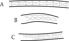
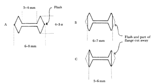
Two of the categories require further clarification: lead profile and mark shape. Close observation reveals that most of the medieval leads have differing profiles on the surface of the panel. The literature suggests that a 2 faceted face is the lead’s original cast appearance.[1] Other profiles are created by planing the lead (fig. 1). Most of these planed faces result in a three or more sided profile, creating a multi-faceted appearance. All leads have been categorised according to the number of facets that can be seen on the profile.
Figure 1: A diagram showing different types of medieval leads. (Barry Knight, 1983). No Type C leads were observed in the NV panels.
This report also considers the appearance of each mark on the lead, which generally fall into fairly defined shape categories. Figure 2 provides the viewer with an illustration of each main mark shape for reference.
Figure 2: Examples of (A) engrailed shapes found on 4BC9, (B) wavy shapes found on 2AB11 and line shapes found on 10c3.
Some lines were difficult to categorise in terms of the shapes, these were recorded as ‘irregular’. Two marks found on the side of the lead (see 2AB12) appeared in a distinct sawtooth pattern, these were classified as ‘jagged’ marks and are likely caused by damage caused during later restoration.
As a last note, left and right in relation to panels are described as though looking at the window from the inside of a building, even when describing the reverse of the panel. For the 2AB panels, these were described by orienting the panel with the long curved side at the bottom, regardless of orientation within the window.
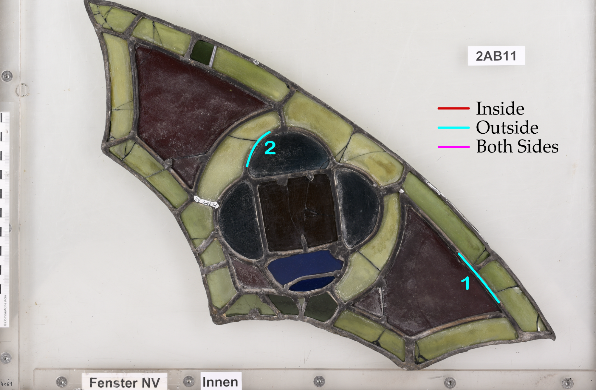
Figure 3: 2AB11 in transmitted light.
Figure 4: Location of marks appearing on 2AB11.
No marks could be seen on the inside of the panel.
2 marks can be distinguished on the outside of the panel, 2AB11-1o (fig. 5) occurring on the left hand side of the panel and the 2AB11-2 (fig. 6) in the centre of the panel, both on 5mm leads.
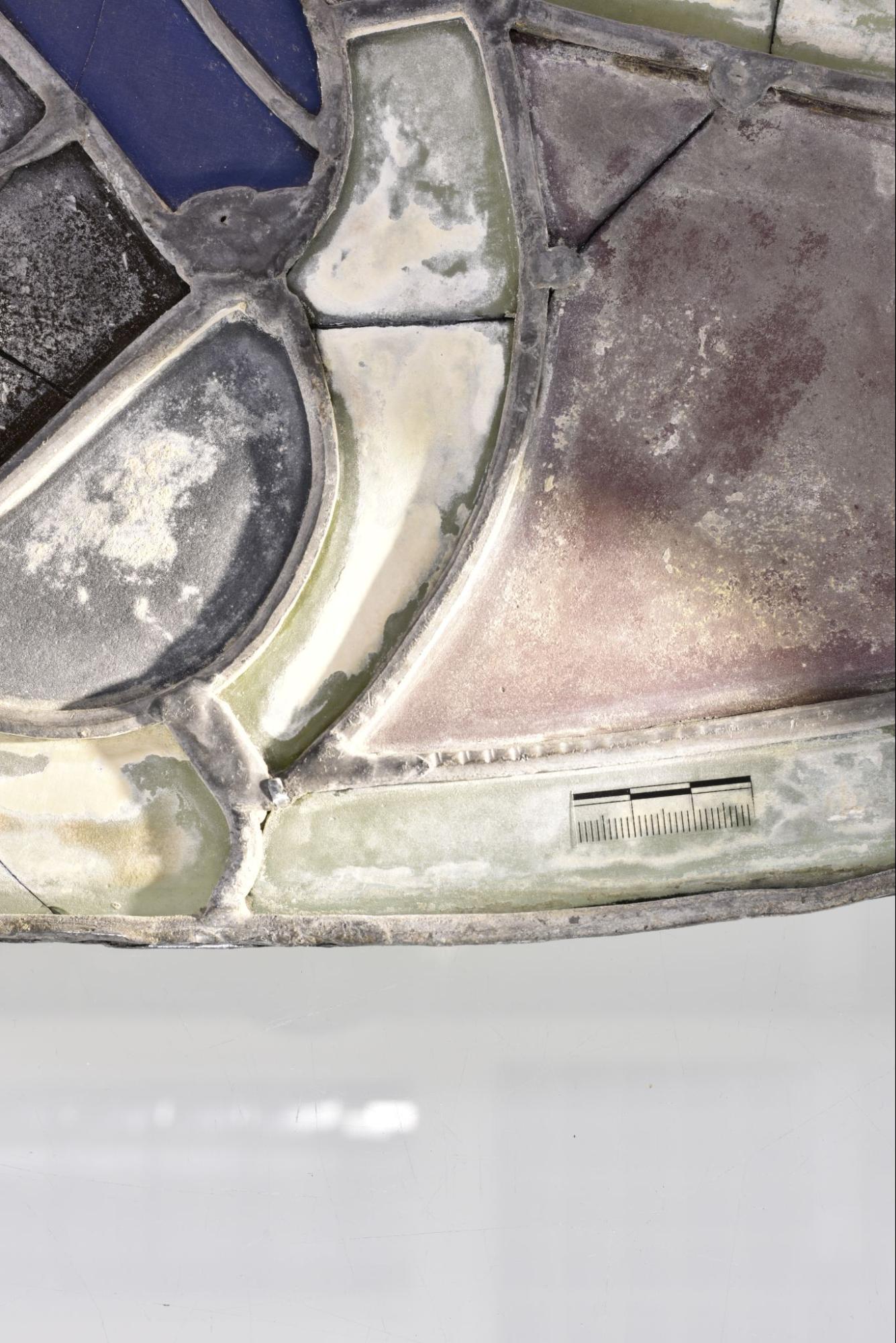
Figure 5: Mark 2AB11-1o.
Figure 6: Mark 2AB11-2o.
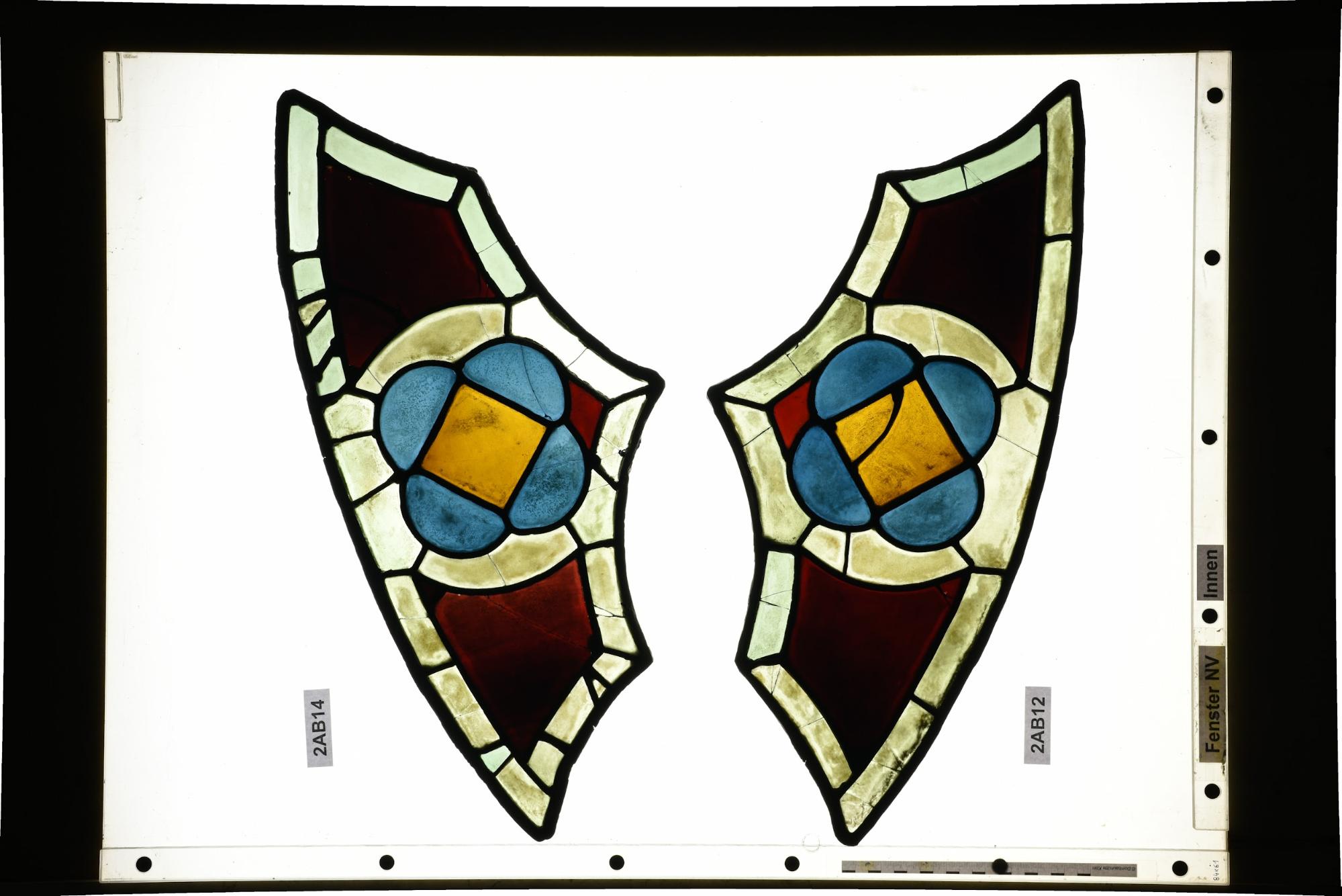
Figure 7: 2AB12 in transmitted light.
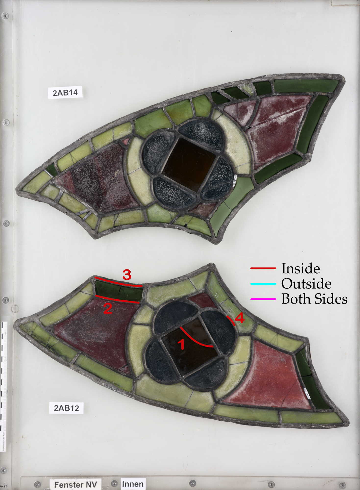
Figure 8: Location of marks appearing on 2AB12.
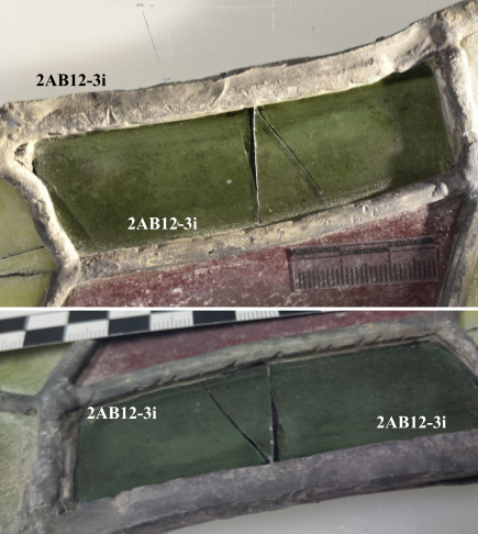
All the marks found on this panel appear on the inside, with 2 marks (fig. 9 & 10)appearing on the left-hand side of the panel and 2 more appearing in the centre of the panel. The jagged marks on the left (2AB12-2 and 2AB12-3, fig. 11) are likely due to a previous restoration intervention as the lead is surrounding a later insert. The marks present are also on the very edge of the flange, which is not seen in other marked leads, again suggesting that they occurred during later intervention.
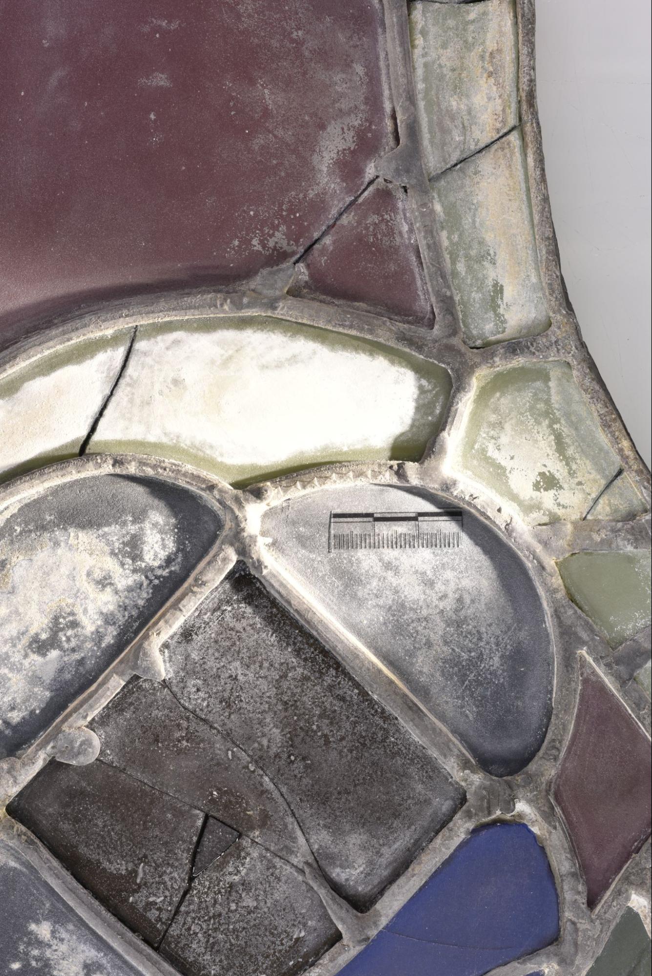
Also of note is 2AB12-1 (fig. 9) which appears in the centre of the panel. It is clearly a mending lead, having a width of 3m; the planed surface and level of corrosion suggests that it is medieval in origin. The marks also appear as regular lines, with no deformation of the overall shape which can be seen in other mark types.
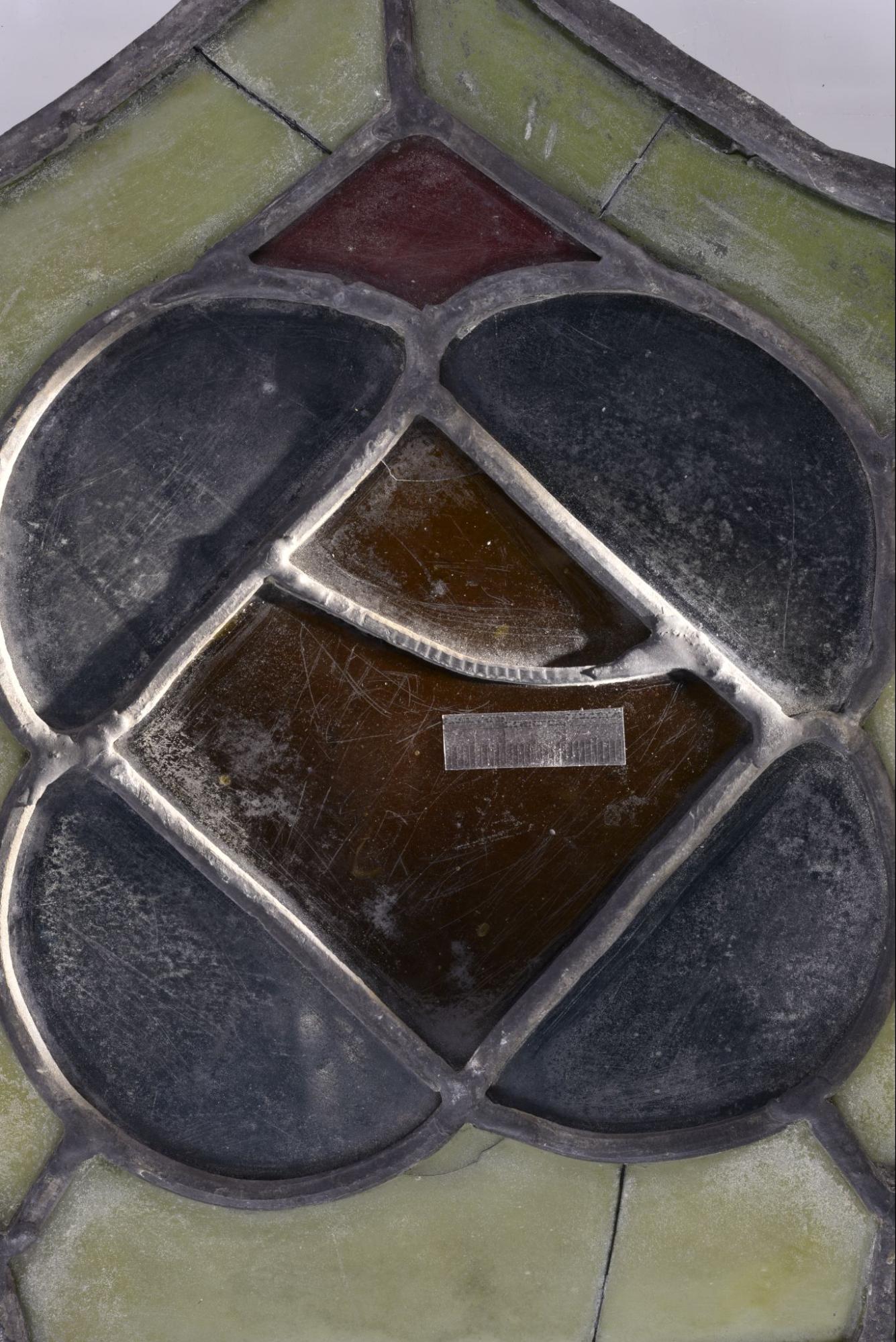
Figure 9: Mark 2AB12-1i.
Figure 10: Mark 2AB12-4i.
Figure 11: Mark 2AB12-2i and 3i. These are difficult to see in the bird’s eye view photography (above) so a side view photograph of 2AB12-3i has been included.
No marks could be seen on the outer side of the panel.
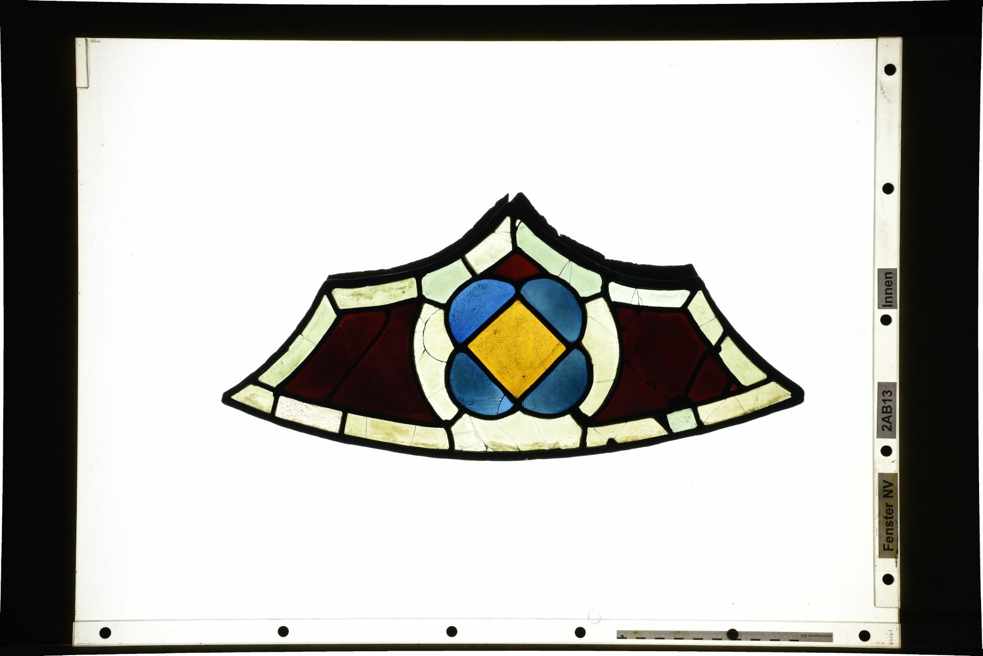
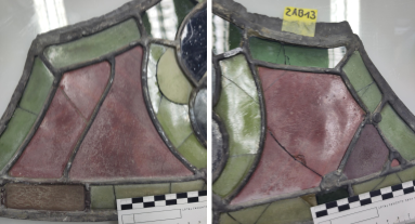
Figure 12: 2AB13 in transmitted light.
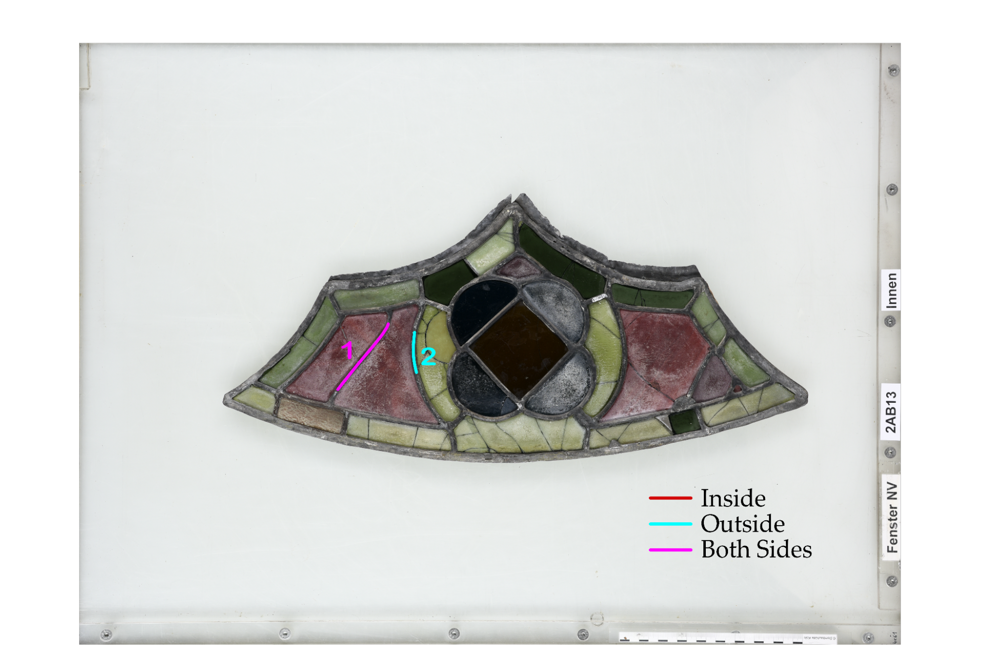
Figure 13: Location of marks appearing on 2AB13.
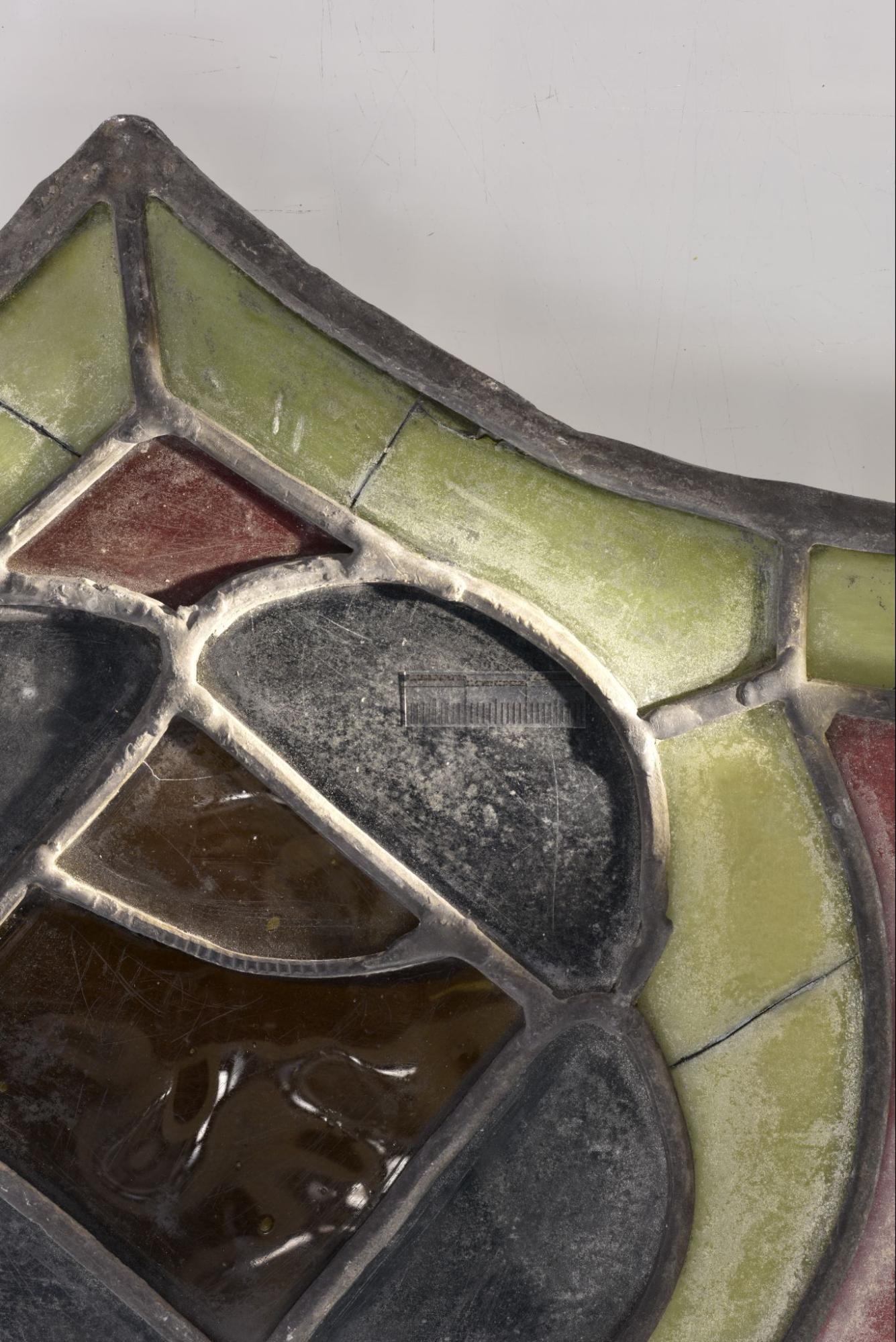
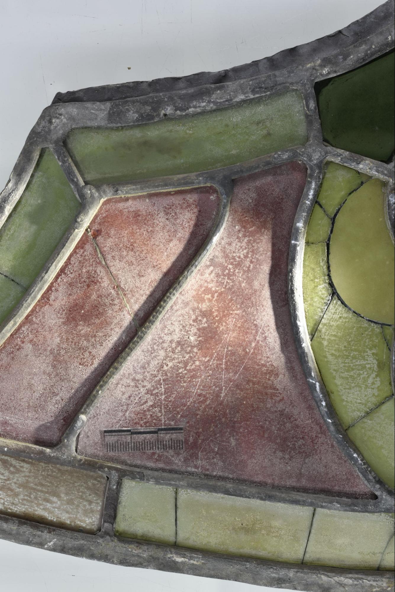
Only 1 mark is present on this side (fig 14.), appearing on the right hand side of the panel. The same mark covers the top and left side, almost obscuring the planed shape of the lead. The planed surface of the lead and level of corrosion suggests that 2AB13-1 is medieval in origin; the 3.5mm width of the lead and its place within the lead matrix (fig. 15) indicate that it is a mending lead. Like 2AB12-1, the marks also appear as regular lines, with no deformation of the overall shape which can be seen in other mark types.
Figure 14: Mark 2AB13-1i.
Figure 15: A comparison of the two red areas in the panel. The difference in design and visible damage to both pieces suggests 2AB13-1 is a mending lead.
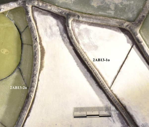
2AB13-1 has similarly shaped marks on the back of the lead. Marks also appear on 2AB13-2 which is located in the same area of the panel. The marks that appear on this lead are bigger and fainter than the other marks found on this panel.
Figure 16: Marks 2AB13-1o and 2AB13-2.
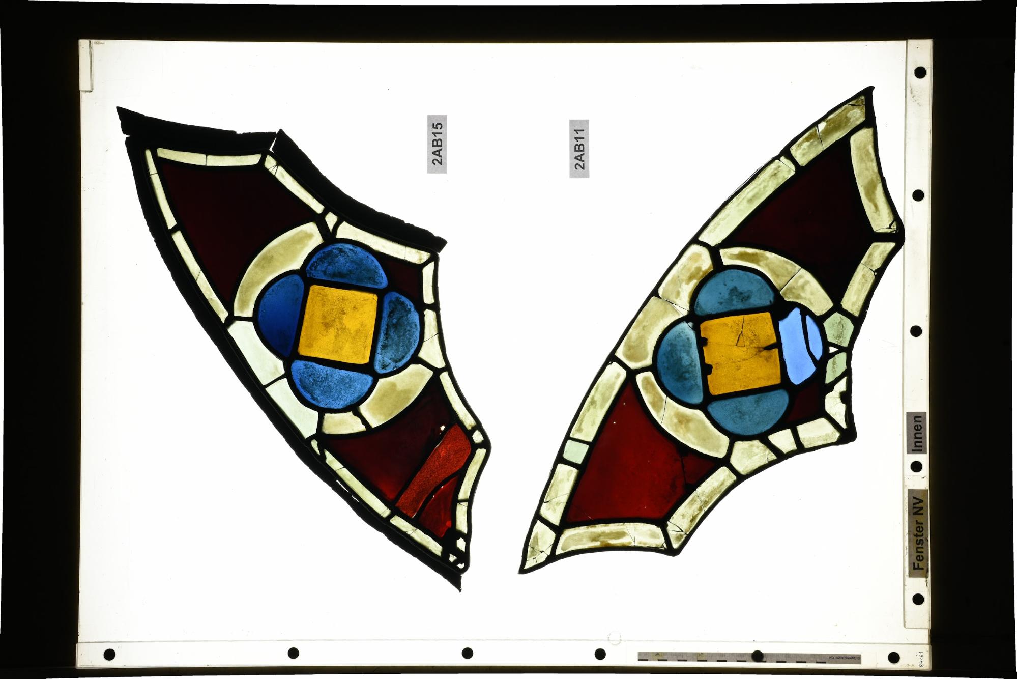
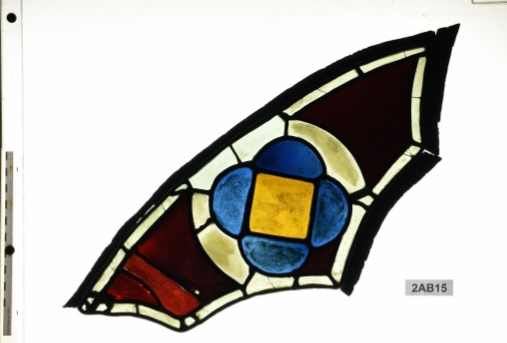
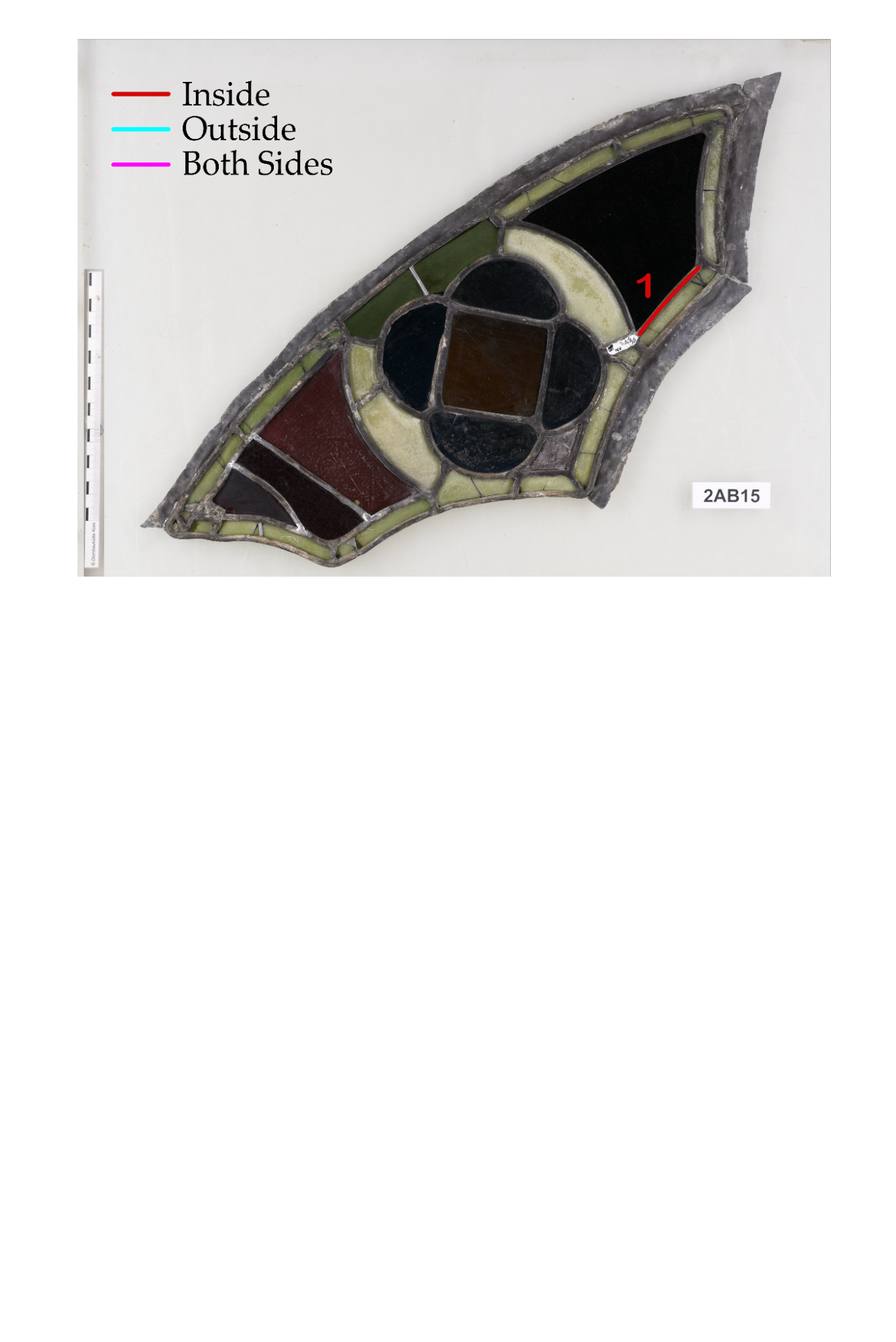
Figure 17: 2AB15 (right panel) in transmitted light.
Figure 17: Location of marks appearing on 2AB15.
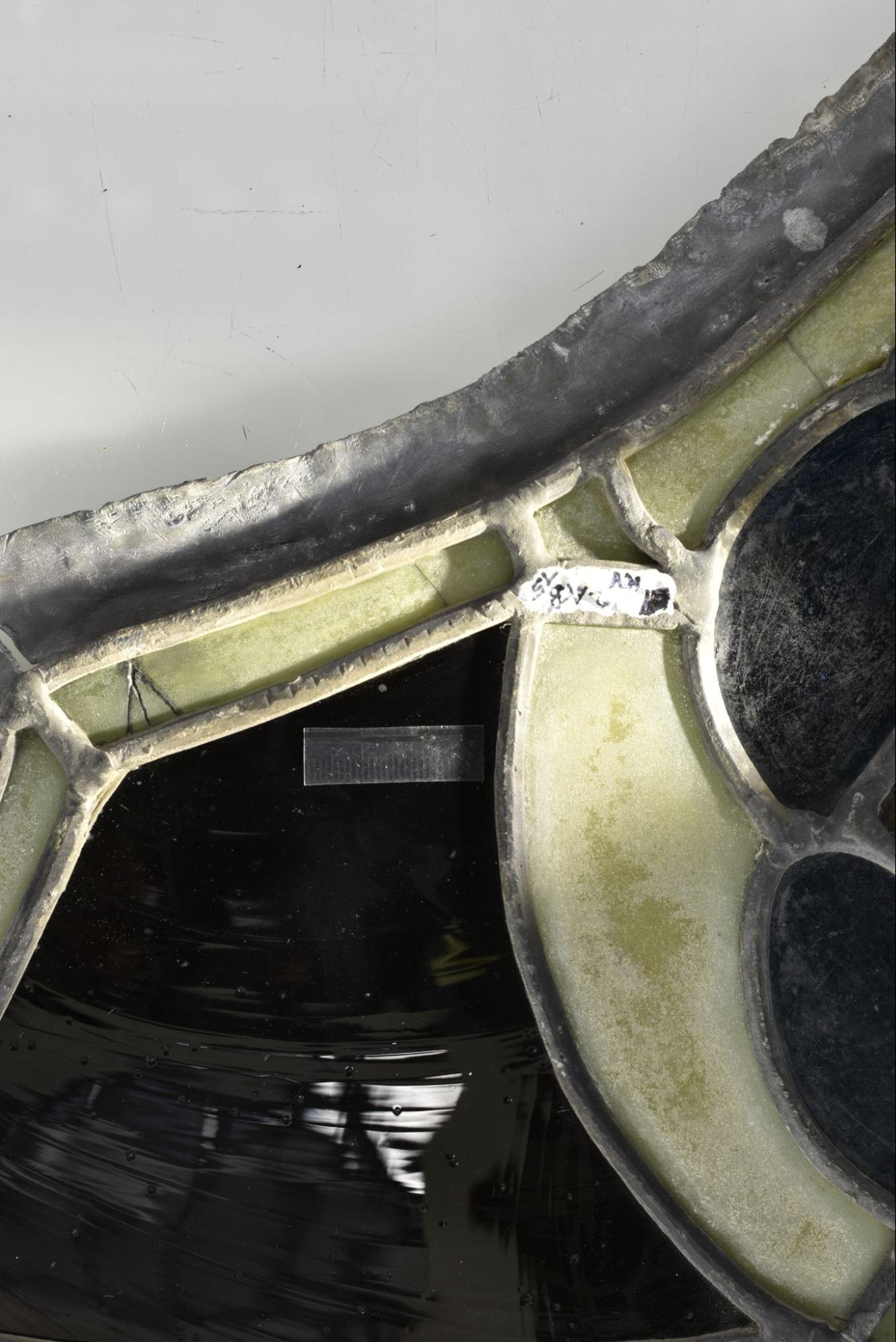
1 mark is present on this side (fig), appearing on the top-right hand side of the panel. The 5mm lead has a noticeably irregular mark shape.
Figure 17: Mark 2AB15-1i.
No marks could be seen on the outer side of the panel.
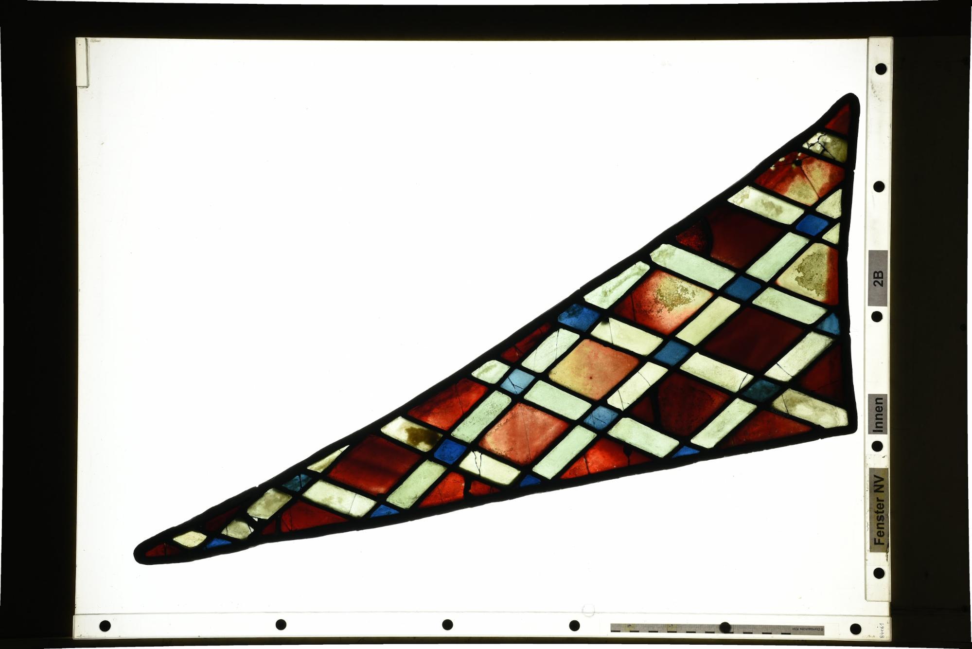
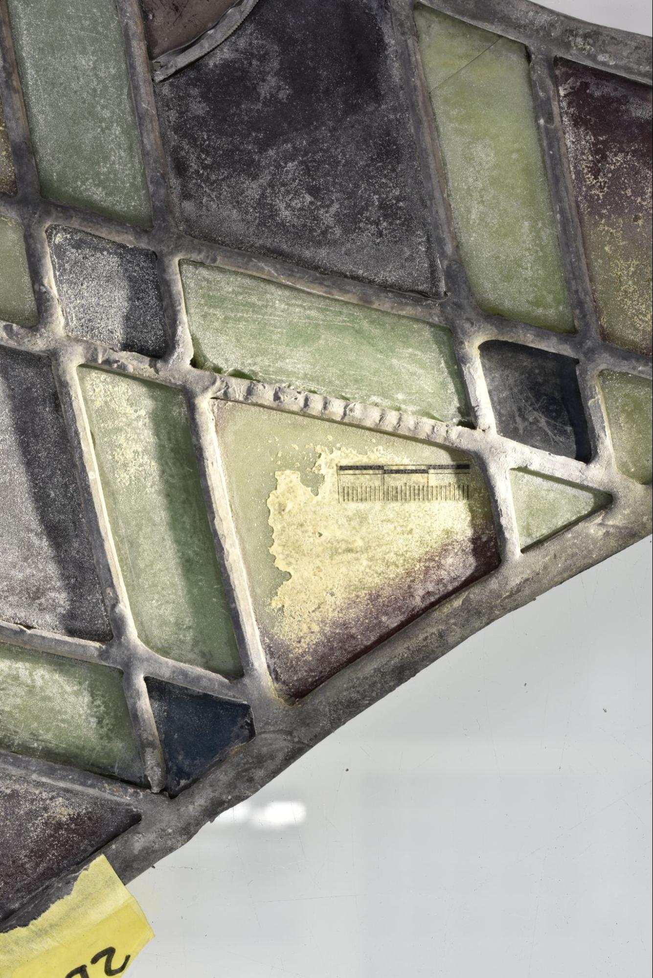
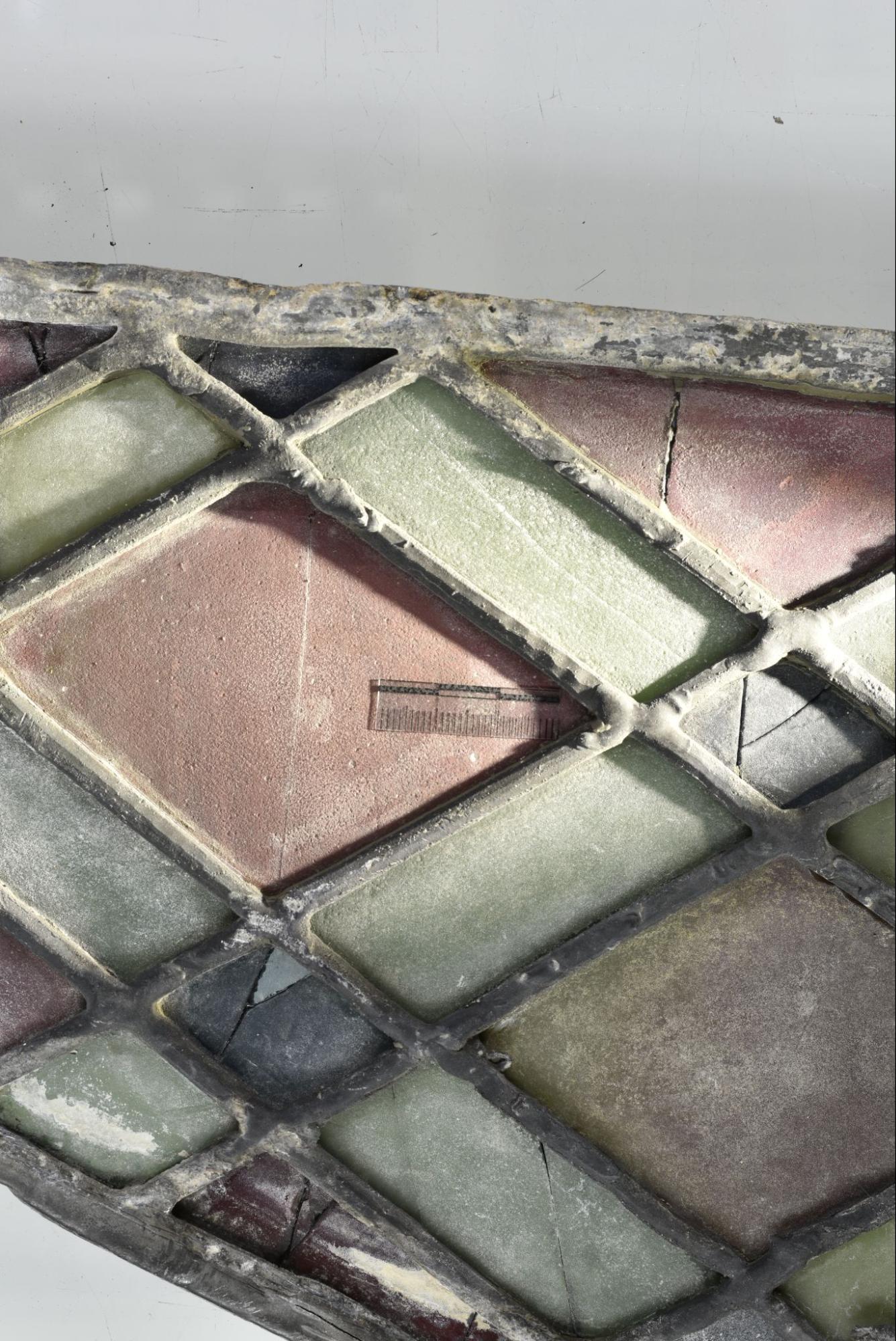
Figure 18: 2B in transmitted light.
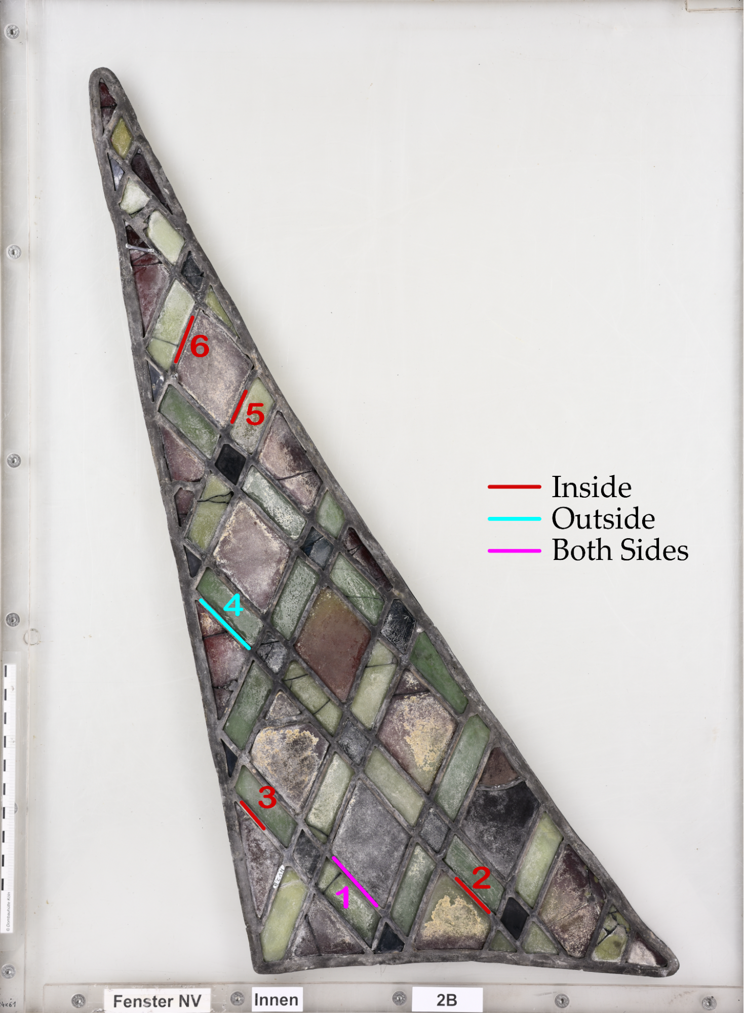
Figure 19: Location of marks appearing on 2B.
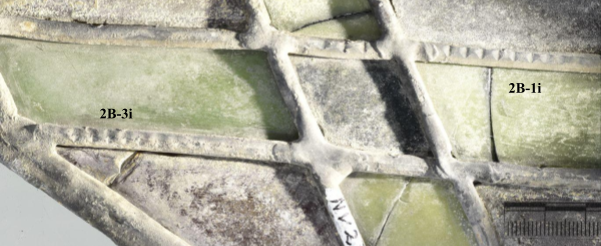
The marks appear on 5 mm leads and all share the same lined mark shape. 3 marks (2B-1 to 2B-3, fig. 20 & 21) are grouped at the bottom, with 2 marks (2B-5 and 2B-6, fig. 22) grouped at the top. Despite initially looking very similar the clarity of the marks varies across the panel, as does the frequency and length.
Figure 20: Marks 2B-1i and 2B-3i.
Figure 21: Mark 2B-2i.
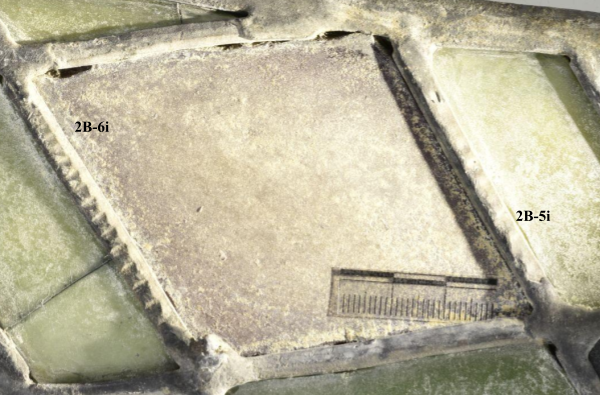
Figure 22: Marks 2B-5i and 2B-6i.
The 2 marks found on the back of the panel are dispersed, with 2B-1 at the panel’s bottom and 2B-4 (fig. 23) other halfway up. The marks are noticeably different in shape to the marks on the front. 2B-1 also has evidence of air bubbles trapped in the casting process on the surface of the lead.
Figure 23: Mark 2B-4i.
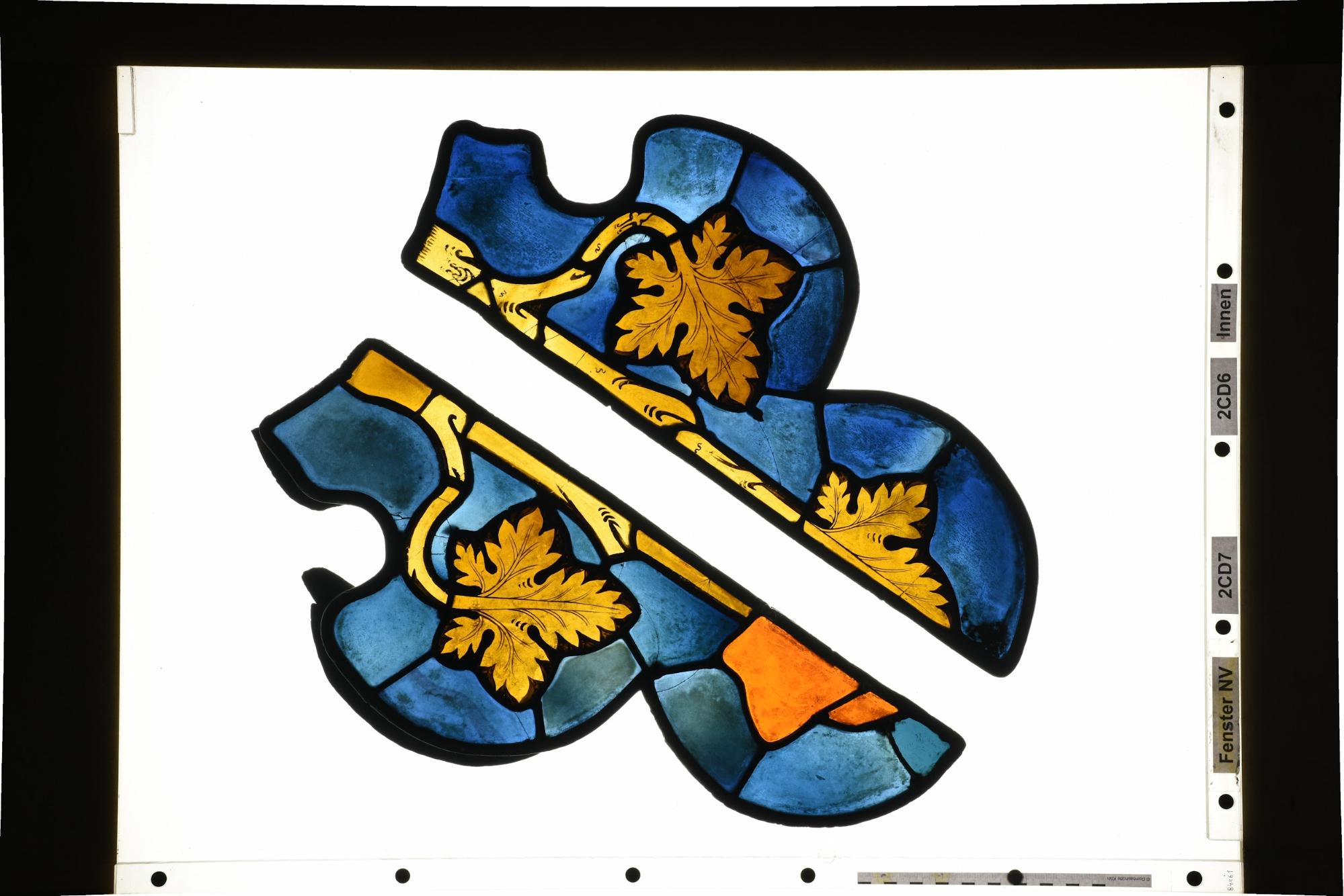
Figure 24: 2CD6 (right-hand panel in photograph) in transmitted light.
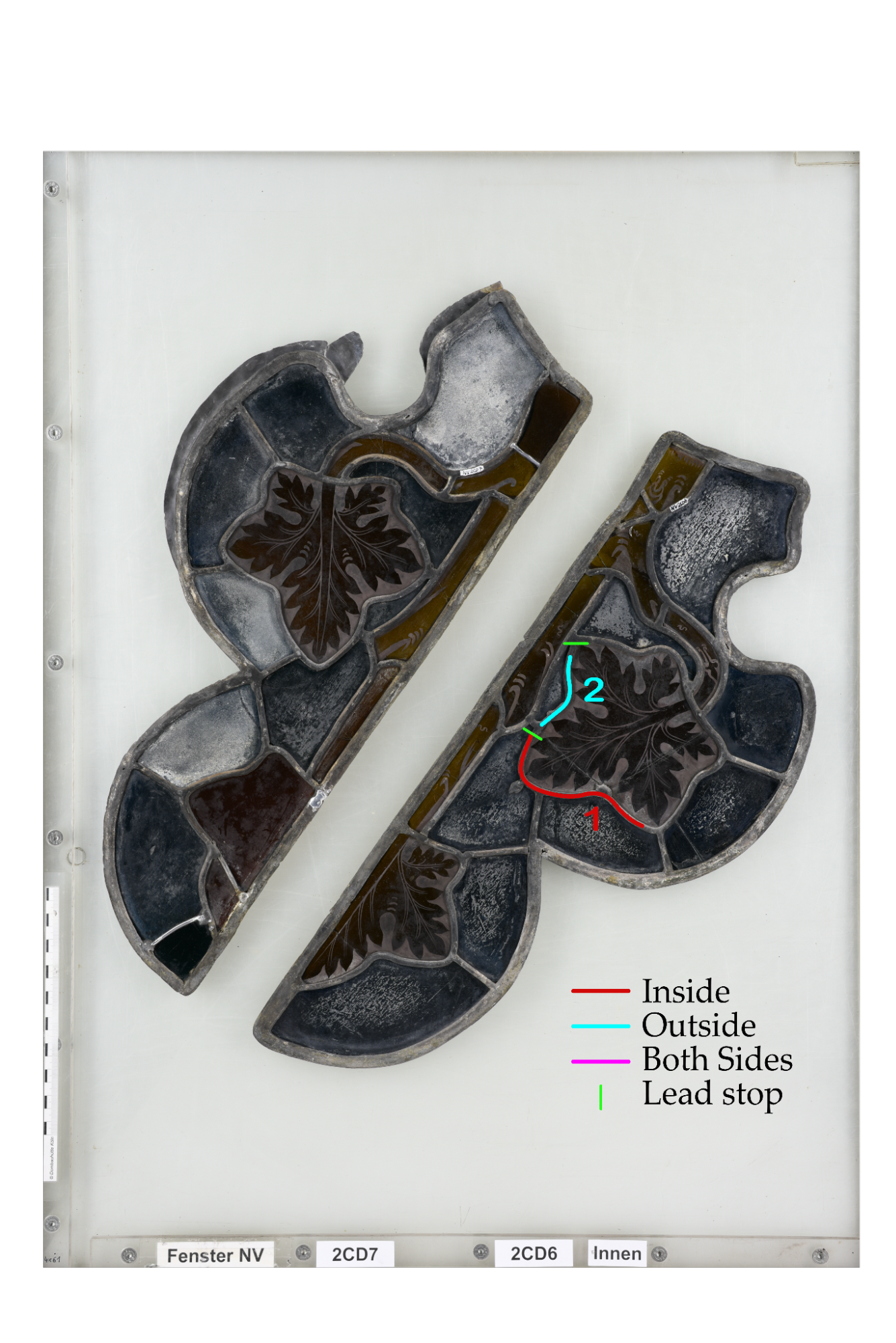
Figure 25: Location of marks appearing on 2CD6.
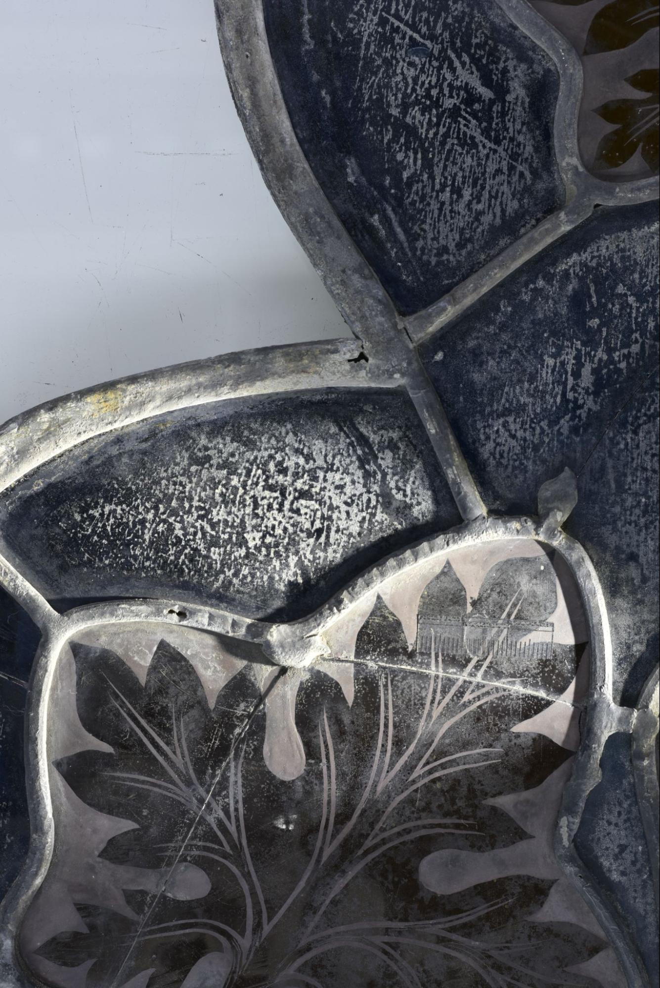
Figure 25: Mark 2CD6-1i.
One mark (fig. 25) appears on the front of the panel, roughly in the centre. It appears on one of the longer leads discussed in this report, which is 420mm long, and appropriately is one of the longest marks found during the investigation. The mark has been made on the top of a 5mm lead. Of particular note is the change in mark shape around the rightmost curve, which bends with the lead, suggesting that the mark was created before the lead was bent.
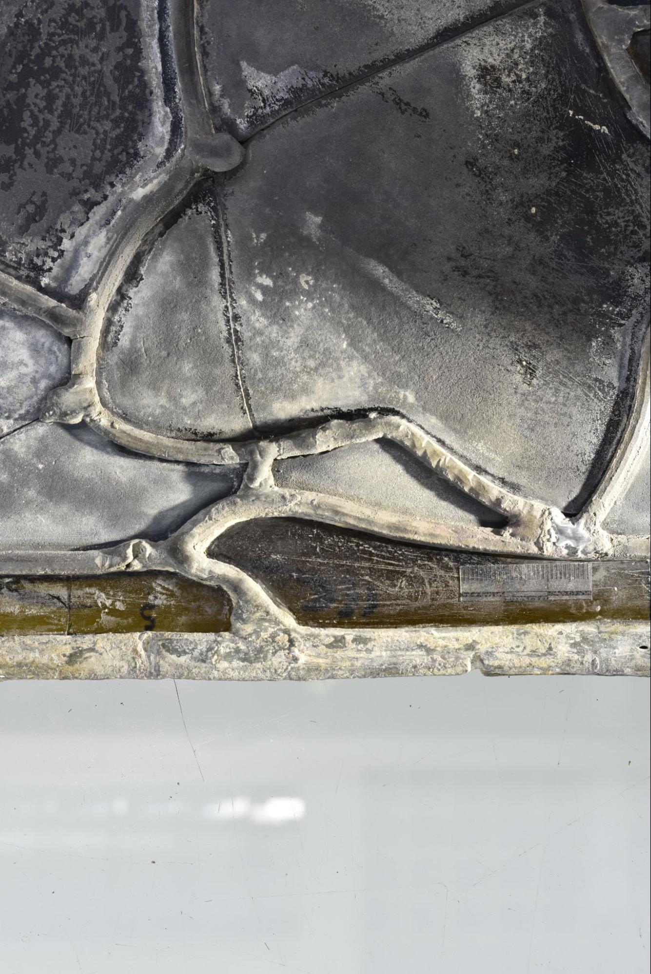
Figure 26: Mark 2CD6-2o.
Although at first glance 2CD6-2 appears to be a part of the same lead as 2CD6-1, further examination reveals that they are actually two separate leads joined together, both 5mm. The mark on 2CD6-2 (fig. 26) is much more irregular and appears on the sides of the lead as opposed to the top.
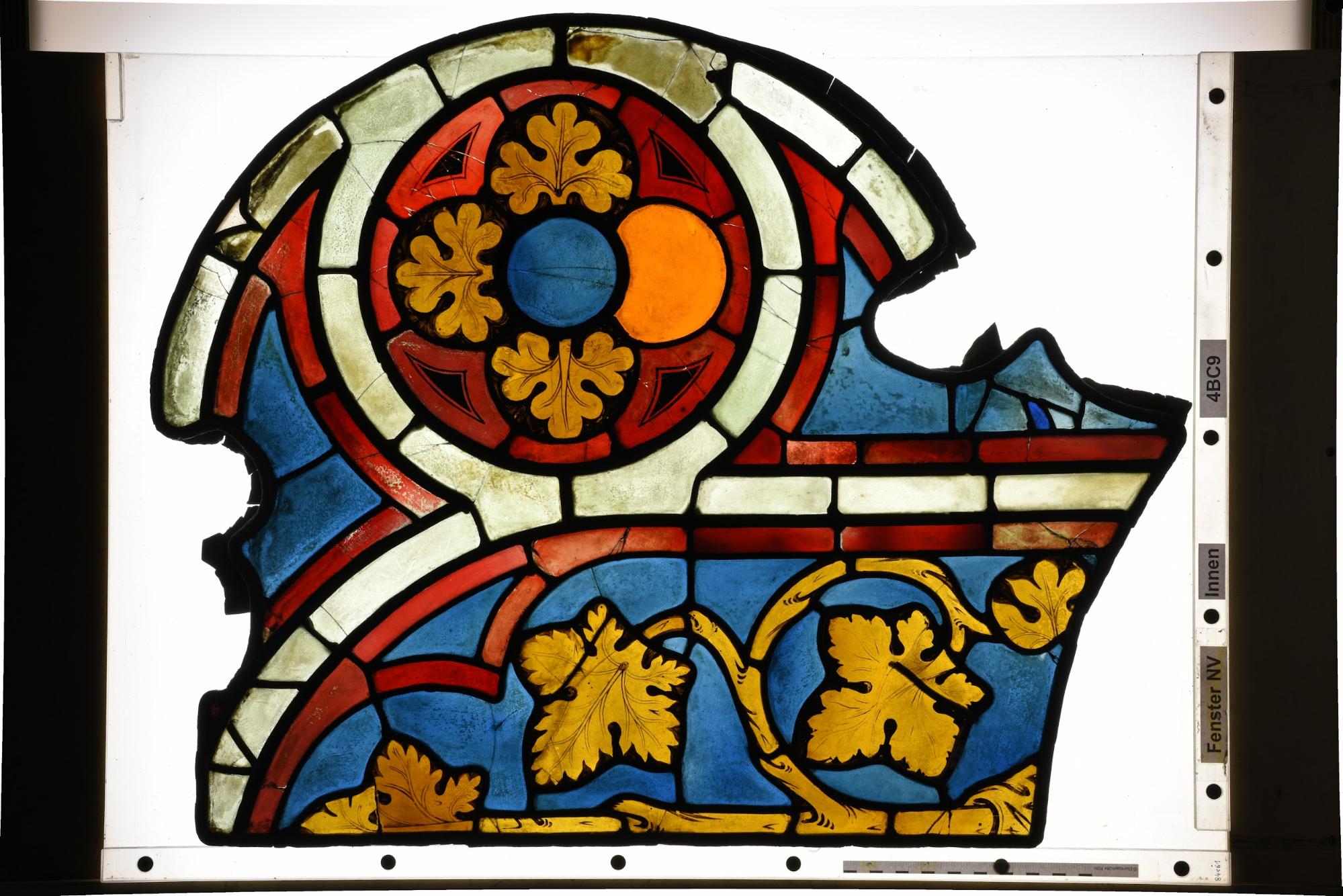
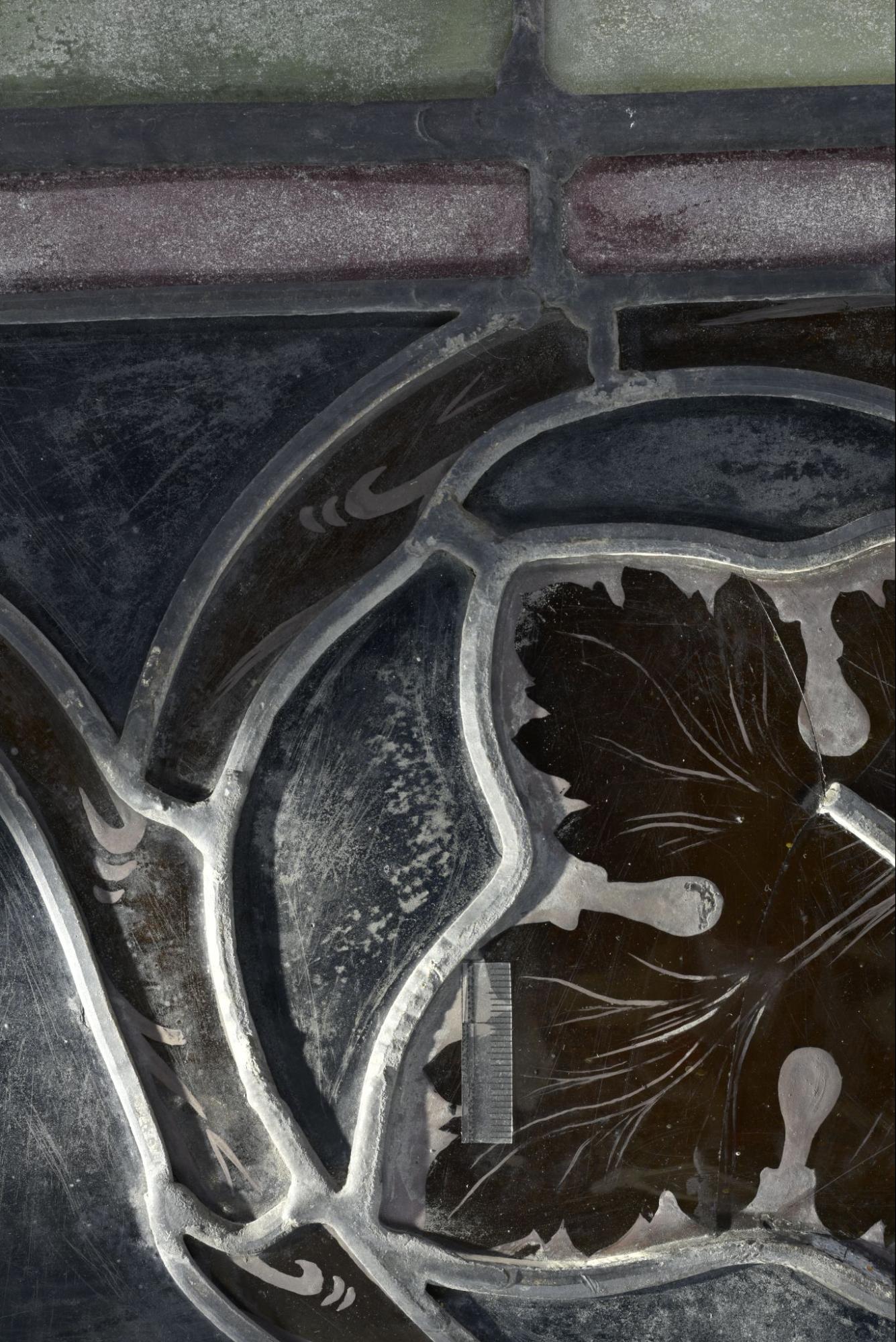
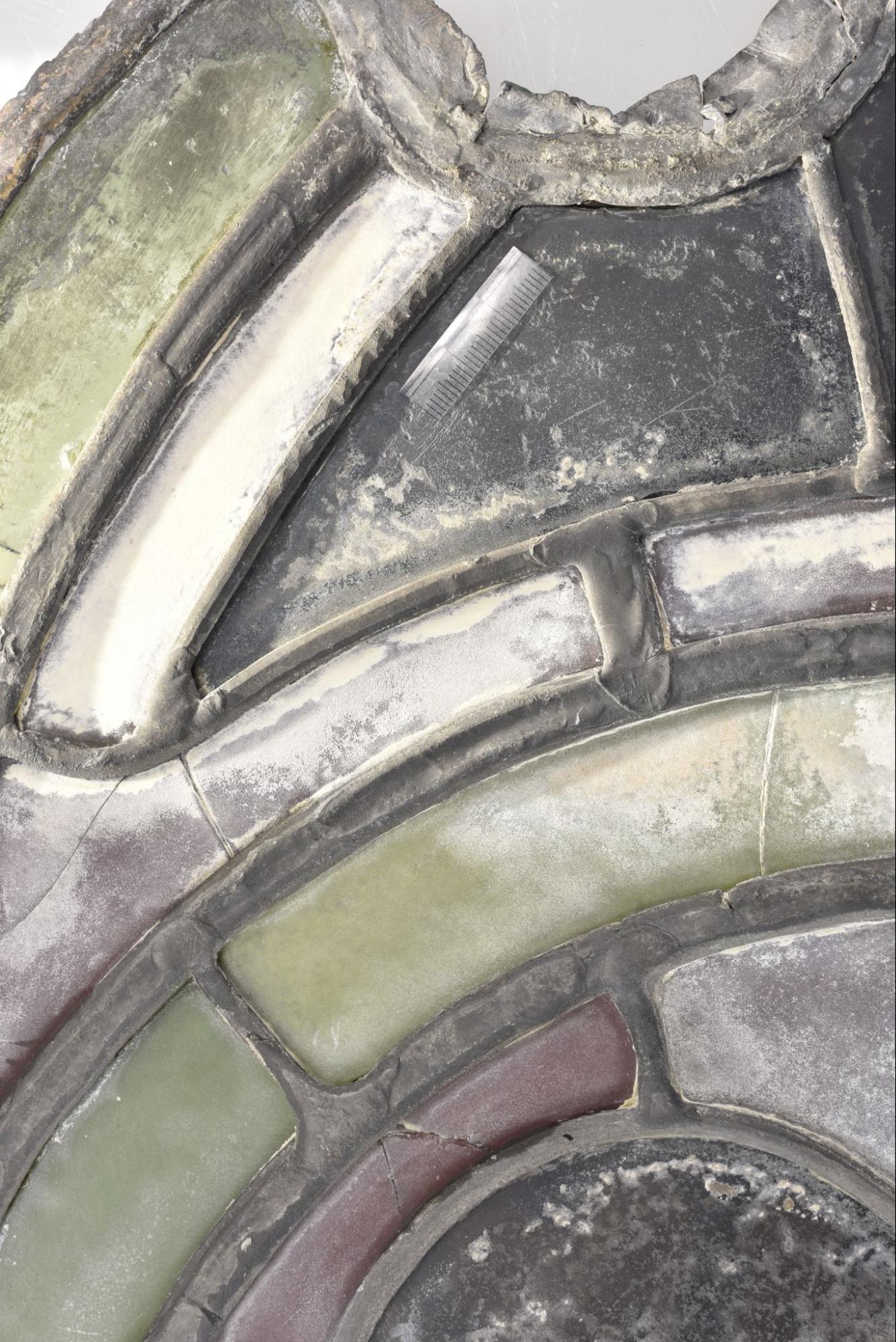
Figure 27: 4BC9 in transmitted light.
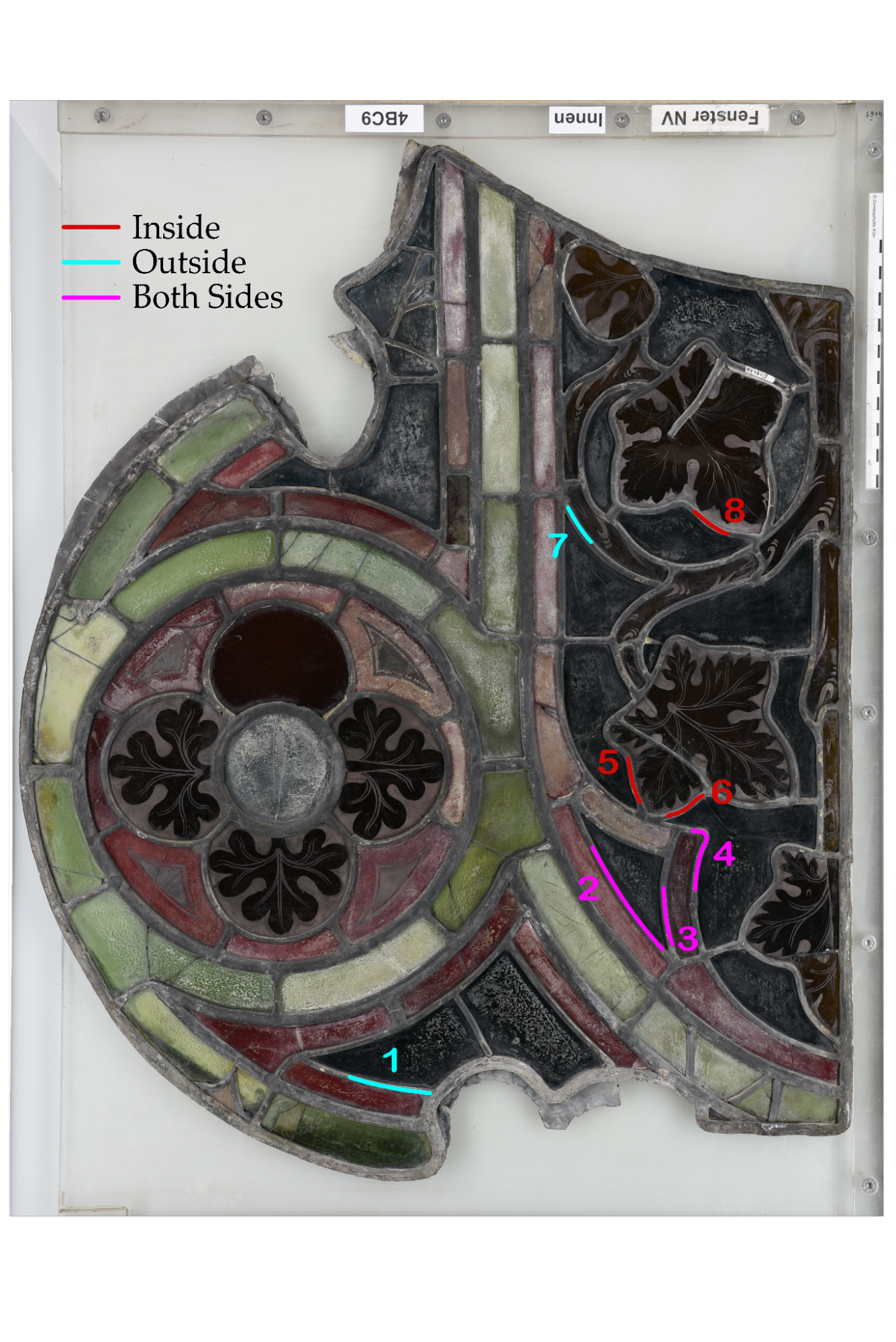
Figure 28: Location of marks appearing on 4BC9.
Marks appear in two distinct areas, both found on the right hand side of the panel with an approximately 20 cm gap between them. The lower area has five leads with marks (fig. 29 & 30) and the upper area has one lead with marks (fig. 31), resulting in a total of 6 marks found on the inner side of the panel. All marks appear on 5 mm leads.
The marks vary in shape and positioning. Most of the marks appear as engrailed indentions, except for 4BC9-3 which has wavy marks. The depth and precision of lines varies across the panel, as does the positioning. Both 3-sided leads (4BC9-1 and 4BC9-3) have marks on the top, with 4BC9-3 also having faint marks on the left side. 4BC9-6 is unusual in that both sides of the lead seem to have marks.
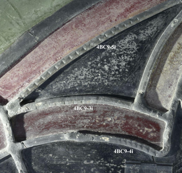
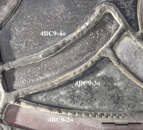
Figure 29: Marks 4BC9-2i, 4BC9-3i and 4BC9-4i.
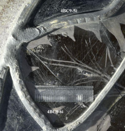
Figure 30: Marks 4BC9-5i and 4BC9-6i.
Figure 31: Mark 4BC9-8i.
The marks appear in three distinct areas in the same positions as the marks found on the inside of the panel, with three towards the bottom, and one towards the top. The exception is 4BC9-7 at the bottom-left of the panel. This makes a total of 5 marks on this side of the panel, all appearing on 5 mm leads.
The marks on this side are largely wavy in appearance, except for 4BC9-1, which is too irregular to determine a distinguishable shape. In general the marks are reasonably clear on this side of the panel.
Figure 32: Mark 4BC9-1o.
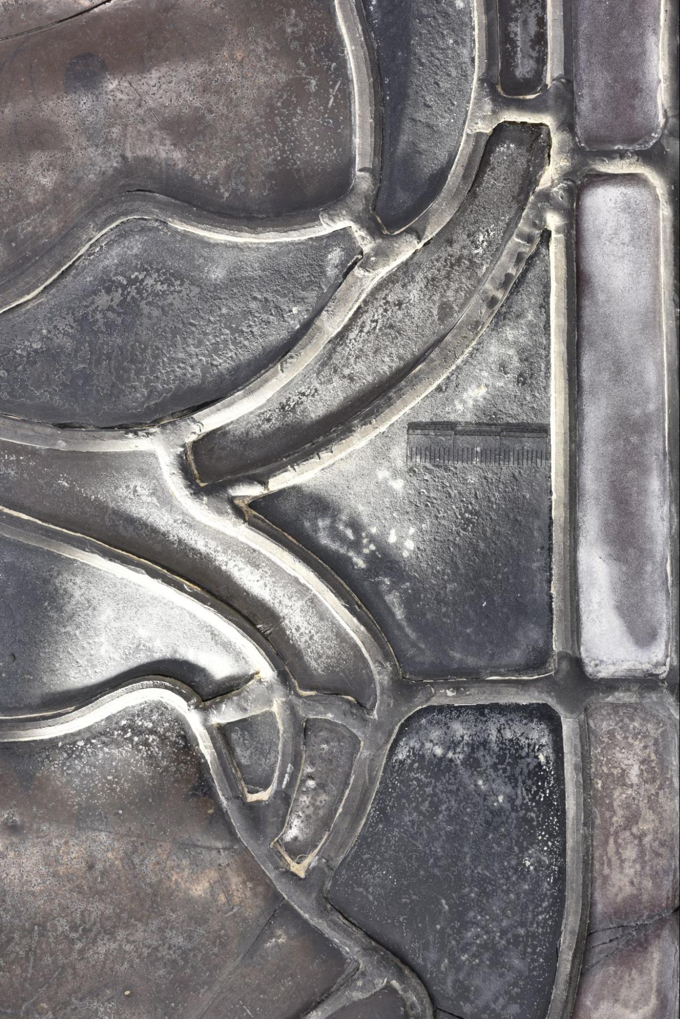
Figure 33: Marks 4BC9-2o, 4BC9-3o and 4BC9-4.
Figure 32: Mark 4BC9-1o.
Figure 33: Location of marks appearing on 4BC9.
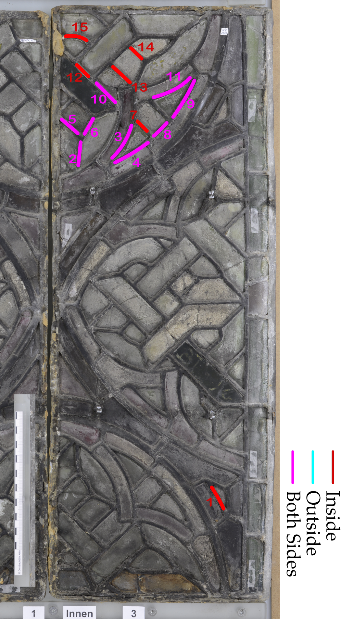
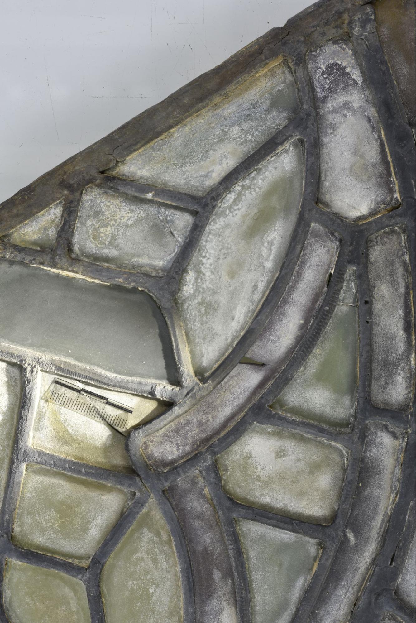
This panel has the most marks of any surveyed, with almost twice the number of any other panel. The marks are largely concentrated at the top of the panel, with a single one (10c3-1i) appearing at the bottom. All marks appear on the 5mm lead and are also made up of evenly spaced lines, about a millimetre apart. Unlike other panels there is no distinct variation between mark ‘shapes’. Although this panel has many short marks when compared to the data collected from other panels this is due to the presence of many short leads within the panel’s matrix design. In fact, many marks observed stretch the whole length of the lead. The difference between this panel and others suggests that possibly a different technique was used to create the marks on these leads.
Figure 34: Mark 10c3-1i.
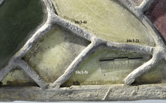
Figure 35: Marks 10c3-2i, 10c3-5i and 10c3-6i.
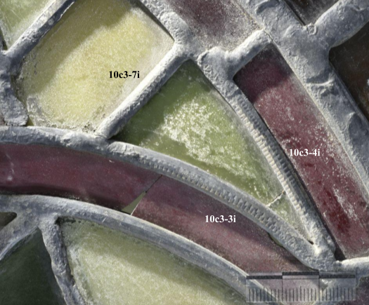
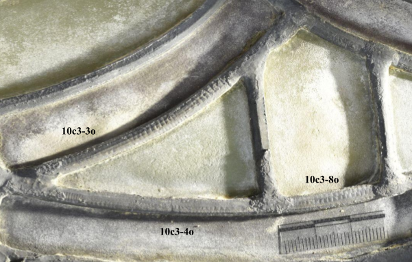
Figure 36: Marks 10c3-3i, 10c3-4i and 10c3-7i.
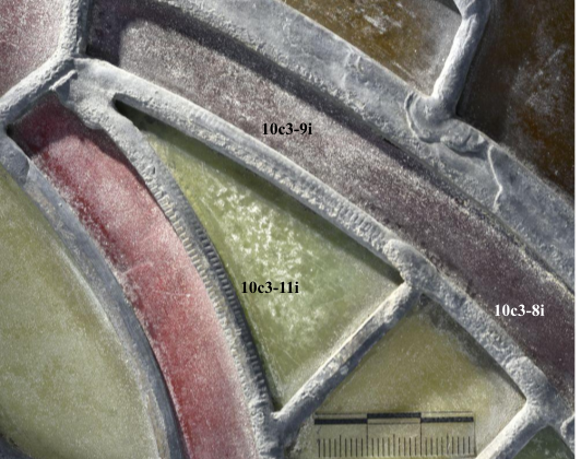
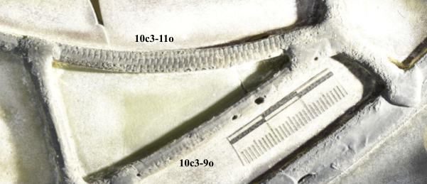
Figure 37: Marks 10c3-8i, 10c3-9i and 10c3-11i.
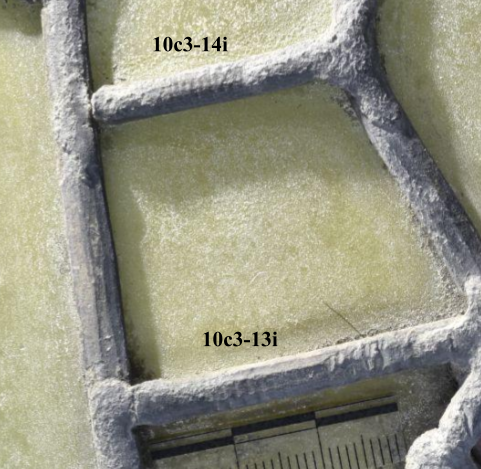
Figure 38: Marks 10c3-13i and 10c3-14i.
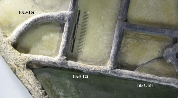
Figure 39: Marks 10c3-10i, 10c3-12i and 10c3-15i.
The marks on the outside are very similar in appearance to the marks on the inside of the panel, appearing exclusively on the back of marked 5mm leads. They are also all clustered at the top of the panel, appearing in a 15 x 10 cm area.
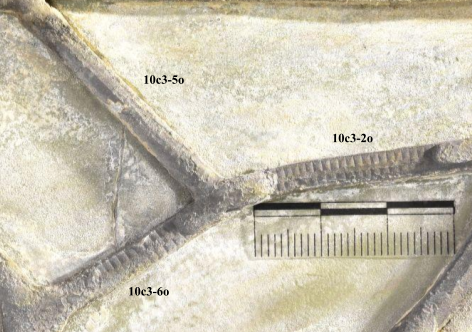
Figure 40: Marks 10c3-2o, 10c3-5o and 10c3-6o.
Figure 41: Marks 10c3-3o, 10c3-4o and 10c3-8o.
Figure 42: Marks 10c3-9o and 10c3-11o.
Figure 43: Mark 10c3-10o.
A total of 55 marks were recorded across 8 panels, ranging in length from 7mm to 123mm, for full data tables, please refer to Appendix I. There was a lot of variation between different marks, however there were some commonalities. None of the marks appeared on solder and could frequently be seen to disappear under solder joints so it is likely that the marks were created before the leads were used for glazing, and certainly before any solder had been applied. In some cases the marks seem to bend with the lead (e.g. 2CD6-1i); this again suggests that they were created before the leads were manipulated for glazing.
Figure 44: This pie chart shows which side of the panel each mark was found on.
Most of the marks were found on the inside (fig. 42), which might indicate that more finely worked lead faces were deliberately chosen to appear on the inside of the panel for aesthetic reasons. However the sample size is not large enough to strongly argue for this theory, a wider sample size which supports this data would create a more compelling argument. In addition, the visibility of the lead face profile is very poor for any viewpoint within the Dom, so an argument drawing on aesthetic reasoning would need further supporting evidence.
Almost a third of the marks appeared only on the top of the lead (fig. 43). Single marks make up 56.4% of the total, while multiple marks make up the other 44.6%. Although a complete survey of the lead profiles for each panel was not possible, due to the amount of time such a survey would take, we can instead compare these percentages with leads excavated at Glastonbury Abbey. 35.5% of these leads had no evidence of planing at all, 44.7% had just the top planed off, with the remaining multi-faceted leads making up the last 19.8%.[2] If we consider just the planed leads, 69.3% of these had only the top removed (ie. one side), with 30.6% multi-faceted. These values are close to the percentages between single (56.4%) and multiple marks (44.6%) in NV, this similarity suggests a correlation between planing and mark-making on the leads.
Figure 45: This pie chart shows where marks have been located with respect to the leads they appear on.
The most common mark shape takes the form of regular lines, with over half of observed marks fitting within this category (fig. 43). However this data is somewhat skewed by the fact that 10c3 has a disproportionate number of marks, which are also all lines. By removing the 10c3 marks from consideration, we can see that the remaining panels have a much more even distribution of mark shape variations (fig. 44). This possibly suggests that different marks shapes were equally likely to happen during refining. Experimental reconstructions indicate that both wavy and engrailed shapes come from cutting with the blade held at an acute angle to the lead face, possibly to remove thick selvedge material, whereas lines come from pulling a perpendicular along the face in a planing motion which is suggestive of a higher level of refinement. This means that the different mark shapes could act as indication of which techniques were used where, possibly a window-wide analysis could reveal which parts of the window were prioritised in terms of the lead-work.
Figure 46: This pie chart shows the different mark ‘shapes’ identified. See Section 2 for a full description of the mark shapes included in this chart.
Figure 47: This pie chart shows the different mark ‘shapes’ identified, excluding 10c3.
The majority of marks appeared on 5mm leads, which is unsurprising due to their ubiquitousness within the panel (fig. 45). One mark did appear on a doubled 8mm outer lead, but this is likely due to previous restoration interventions. Three marks appeared on 3 and 3.5mm mending leads. This likely indicates that these mending leads are medieval in origin, possibly inserted due to breakage in the workshop, or possibly evidence of later medieval conservation practice. It would be interesting to compare the composition of these leads to other 5mm leads found within the matrix, to try and determine whether they share the same origin. However this would require destructive sampling so may not be appropriate at this time.
Figure 48: This pie chart shows the widths for marked leads, values given in millimetres. The yellow segment refers to 3mm leads which make up 1.8% of total leads included.
Lastly, the data collected on the frequency of the marks is comparable to that collected on mark shape, as the large number of 10c3’s hegemonic marks skews the data. Initially it looks like almost half of the marks (47.3%) are very closely spaced (fig. 45), however when we remove 10c3 from the dataset, the frequencies are more evenly distributed, with most marks appearing 4-5 mm away from each other (fig. 46). In general, the frequencies fall within a small range of 1mm to 6mm and mostly seem to be fairly regular in appearance. While this regularity could be suggestive of machine use, there level of variation between different marks suggests a more human origin.
Figure 49: This pie chart shows the frequency of observed marks, recorded in average distance between each mark (mm).
Figure 50: This pie chart shows the frequency of observed marks, recorded in average distance between each mark (mm), excluding 10c3.
In summary, it is difficult to draw any firm conclusions on what the condition of the marks can tell us about their origin. However when we consider the results of this condition survey with practical reconstructive experiments and the current literature on the subject, the observations made seem to support the conclusion that these marks are largely due to the refining stage of medieval lead came manufacture.
Panel ID | Lead ID | Mark ID | Outside/ Inside | No. of planed surfaces | Lead width (mm) | Mark Length (mm±1) | Mark Shape | Mark Frequency (mm±1) | Position on Lead | Clarity (/5) | Notes |
4BC9 | 4BC9-2 | 4BC9-2i | I | 3 | 5 | 98 | Engrailed | 5 | Top | 5 | |
4BC9 | 4BC9-3 | 4BC9-3i | I | 2 | 5 | 43 | Engrailed | 6 | Side (R) | 4 | |
4BC9 | 4BC9-4 | 4BC9-4i | I | 3 | 5 | 51 | Wavy | 3 | Top and Side | 5 | Small scraping marks apparent |
4BC9 | 4BC9-5 | 4BC9-5i | I | 2 | 5 | 20 | Engrailed | 4 | Side (R) | 3 | |
4BC9 | 4BC9-6 | 4BC9-6i | I | 2 | 5 | 27 | Engrailed | 4 | Side (L) | 2 | |
4BC9 | 4BC9-8 | 4BC9-8i | I | 2 | 5 | 28 | Engrailed | 4 | Over entire lead | 1 | |
4BC9 | 4BC9-1 | 4BC9-1o | O | 3 | 5 | 59 | Irregular | 3.5 | Top and Side | 2 | |
4BC9 | 4BC9-2 | 4BC9-2o | O | 3 | 5 | 54 | Wavy | 4.5 | Top | 5 | |
4BC9 | 4BC9-3 | 4BC9-3o | O | 3 | 5 | 55 | Wavy | 5 | Top | 5 | |
4BC9 | 4BC9-4 | 4BC9-4o | O | 3 | 5 | 23 | Wavy | 4 | Both sides | 3 | |
4BC9 | 4BC9-7 | 4BC9-7o | O | 2 | 5 | 23 | Wavy | 5 | Side (R) | 4 | |
2AB13 | 2AB13-1 | 2AB13-1i | I | 3 | 3.5 | 43 | Lines | 1.5 | Top and Side | 2 | The same mark appears over left and top side |
2AB13 | 2AB13-1 | 2AB13-1o | O | 3 | 3.5 | 68 | Lines | 1 | Top | 2 | |
2AB13 | 2AB13-2 | 2AB13-2o | O | 2 | 5 | 40 | Engrailed | 4 | Side (L) | 1 | |
2AB15 | 2AB15-1 | 2AB15-1i | I | 3 | 5 | 51 | Irregular | 4.5 | Top | 4 | |
2CD6 | 2CD6-1 | 2CD6-1i | I | 3 | 5 | 123 | Engrailed | 4 | Top | 2 | Changes shape as the lead curves. |
2CD6 | 2CD6-2 | 2CD6-2o | O | 3 | 5 | 38 | Irregular | 6 | Both sides | 3 | |
2AB12 | 2AB12-1 | 2AB12-1i | I | 3 | 3 | 43 | Engrailed | 1.5 | Top | 5 | |
2AB12 | 2AB12-2 | 2AB12-2ia | I | 2 | 5 | 28 | Wavy | 5 | Top | 2 | |
2AB13 | 2AB12-2 | 2AB12-2ib | I | 2 | 5 | 63 | Jagged | 6 | Side (R) | 5 | Very irregular frequency |
2AB12 | 2AB12-3 | 2AB12-3i | I | n/a | 8 | 74 | Jagged | 5 | Side (R) | 5 | Lead part of doubled up border, with willow rod core. Profile can't be seen as it is covered in solder. |
2AB12 | 2AB12-4 | 2AB12-4i | I | 2 | 5 | 12 | Wavy | 1 | Top | 1 | |
2B | 2B-1 | 2B-1i | I | 3 | 5 | 34 | Lines | 3.5 | Top | 5 | |
2B | 2B-1 | 2B-1o | O | 3 | 5 | 26 | Engrailed | 5 | Top | 4 | Casting defects apparent on surface |
2B | 2B-2 | 2B-2i | I | 3 | 5 | 50 | Lines | 5 | Top | 4 | |
2B | 2B-3 | 2B-3i | I | 2 | 5 | 20 | Lines | 3 | Side (R) | 1 | |
2B | 2B-4 | 2B-4i | O | 2 | 5 | 20 | Wavy | 5 | Side (L) | 3 | |
2B | 2B-5 | 2B-5i | I | 3 | 5 | 24 | Lines | 4 | Side (R) | 2 | |
2B | 2B-5 | 2B-5i | I | 3 | 5 | 45 | Lines | 3 | Top | 3 | |
10c3 | 10c3-1 | 10c3-1i | I | 3 | 5 | 35 | Lines | 1 | Both sides | 4 | |
10c3 | 10c3-2 | 10c3-2i | I | 4 | 5 | 26 | Lines | 1 | Both sides | 1 | |
10c3 | 10c3-2 | 10c3-2o | O | 3 | 5 | 24 | Lines | 1 | Both sides | 4 | |
10c3 | 10c3-3 | 10c3-3i | I | 4 | 5 | 58 | Lines | 1 | Top and Side | 5 | Along whole length of lead |
10c3 | 10c3-3 | 10c3-3o | O | 3 | 5 | 56 | Lines | 1 | Over entire lead | 5 | |
10c3 | 10c3-4 | 10c3-4i | I | 4 | 5 | 42 | Lines | 1 | Both sides | 5 | |
10c3 | 10c3-4 | 10c3-4o | O | 3 | 5 | 24 | Lines | 1 | Top and Side | 1 | |
10c3 | 10c3-5 | 10c3-5i | I | 2 | 5 | 25 | Lines | 1 | Side (R) | 2 | |
10c3 | 10c3-5 | 10c3-5o | O | 4 | 5 | 24 | Lines | 1 | Over entire lead | 4 | |
10c3 | 10c3-6 | 10c3-6i | I | 4 | 5 | 12 | Lines | 1 | Top and Side | 1 | |
10c3 | 10c3-6 | 10c3-6o | O | 3 | 5 | 19 | Lines | 1 | Both sides | 3 | |
10c3 | 10c3-7 | 10c3-7i | I | 3 | 5 | 12 | Lines | 1 | Both sides | 4 | |
10c3 | 10c3-8 | 10c3-8i | I | 4 | 5 | 8 | Lines | 1 | Top | 1 | |
10c3 | 10c3-8 | 10c3-8o | O | 3 | 5 | 23 | Lines | 1 | Top and Side | 4 | |
10c3 | 10c3-9 | 10c3-9o | O | 3 | 5 | 42 | Lines | 1 | Top | 1 | |
10c3 | 10c3-9 | 10c3-9i | I | 4 | 5 | 51 | Lines | 1 | Over entire lead | 4 | |
10c3 | 10c3-10 | 10c3-10i | I | 2 | 5 | 9 | Lines | 1 | Side (L) | 2 | |
10c3 | 10c3-10 | 10c3-10o | O | 3 | 5 | 35 | Lines | 1 | Side (L) | 3 | |
10c3 | 10c3-11 | 10c3-11i | I | 3 | 5 | 50 | Lines | 1 | Both sides | 5 | |
10c3 | 10c3-11 | 10c3-11o | O | 3 | 5 | 54 | Lines | 1 | Top and Side | 4 | |
10c3 | 10c3-12 | 10c3-12i | I | 2 | 5 | 7 | Lines | 1 | Side (L) | 1 | |
10c3 | 10c3-13 | 10c3-13i | I | 4 | 5 | 21 | Lines | 1 | Top and Side | 3 | |
10c3 | 10c3-14 | 10c3-14i | I | 3 | 5 | 8 | Lines | 1 | Over entire lead | 1 | |
10c3 | 10c3-15 | 10c3-15i | I | 3 | 5 | 27 | Lines | 1 | Over entire lead | 3 | |
2AB12 | 2AB12-1 | 2AB12-1o | O | 4 | 5 | 15 | Wavy | 4 | Top | 3 | |
2AB12 | 2AB12-2 | 2AB12-2o | O | 4 | 5 | 17 | Engrailed | 4 | Top | 4 |
[1] Barry Knight, “Researches on Medieval Window Lead,” Journal of the British Society of Master Glass-Painters 18, no. 1 (1983): 50.
[2] Pam Graves, “The Lead Cames from Glastonbury Abbey,” The Glastonbury Abbey Archaeological Archive Project (York: Archaeology Data Service, 2011) https://doi.org/10.5284/1022585. Data amended to be a percentage out of medieval lead found, as original percentages refer to a wider data set.