Conservation Report
Robin Henderson
Department of History of Art, University of York
21st May 2025
MA Assessed Report for HOA00045M Advanced Techniques in Stained Glass Conservation
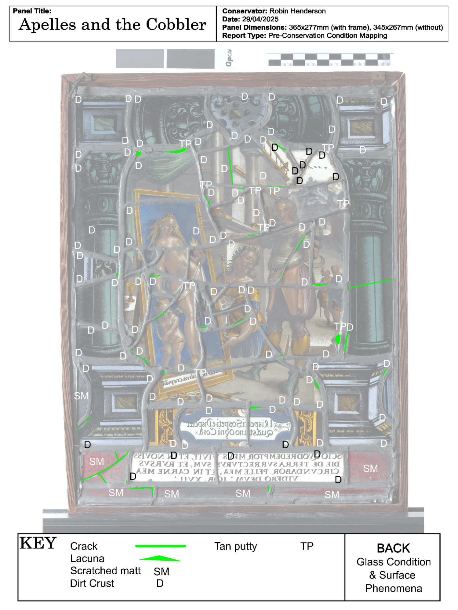
5.3.3. Other surface phenomena
6. Handling guidance and future care
7. Suggestions for Future Conservation
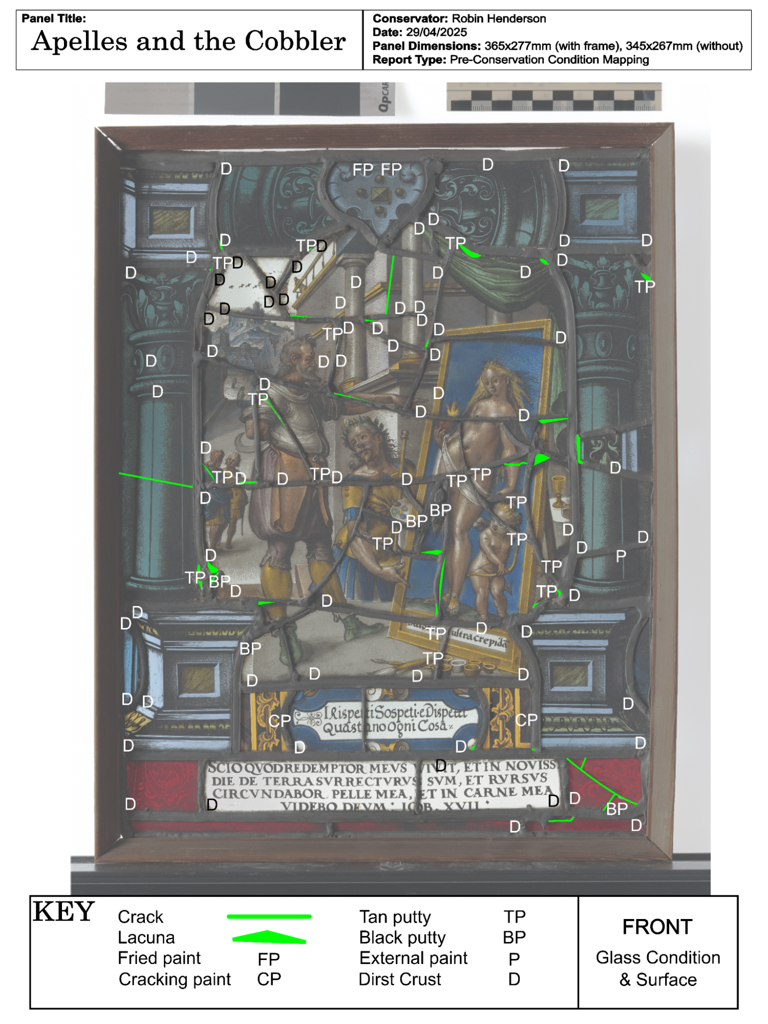
Appendix II: Pre-conservation Mapping
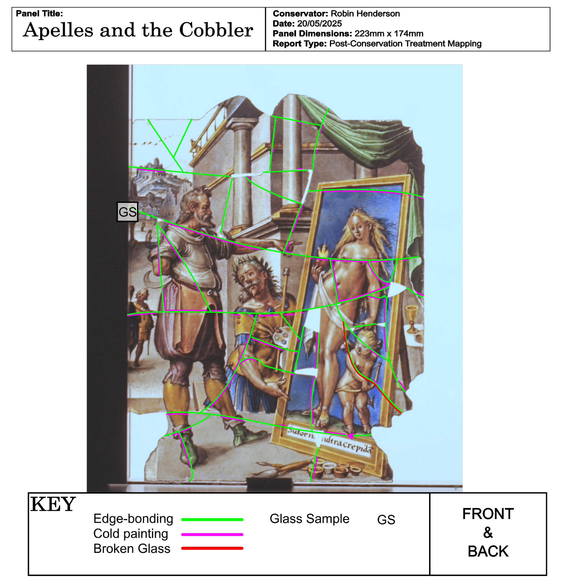
Appendix III: Post-conservation Mapping
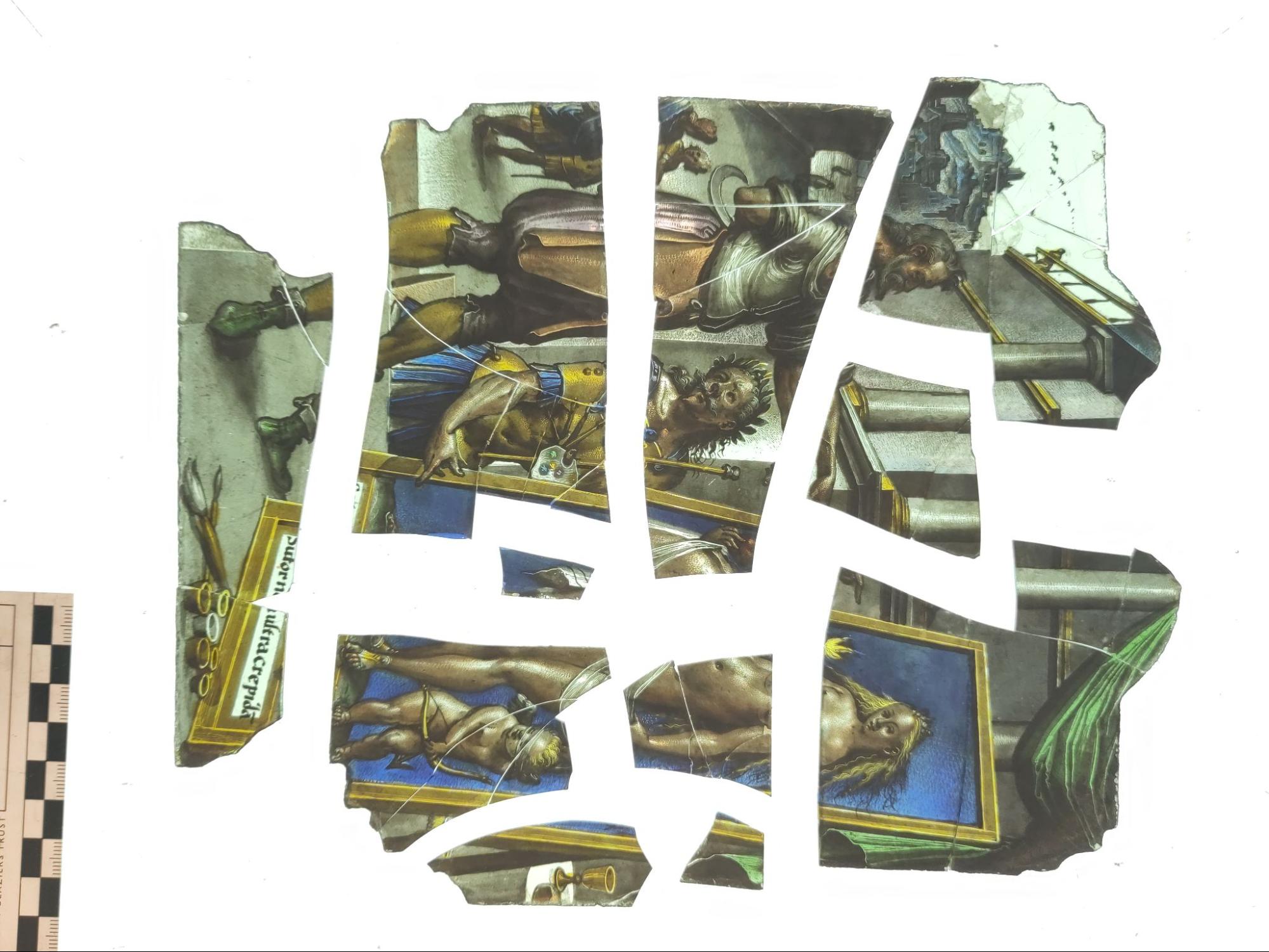
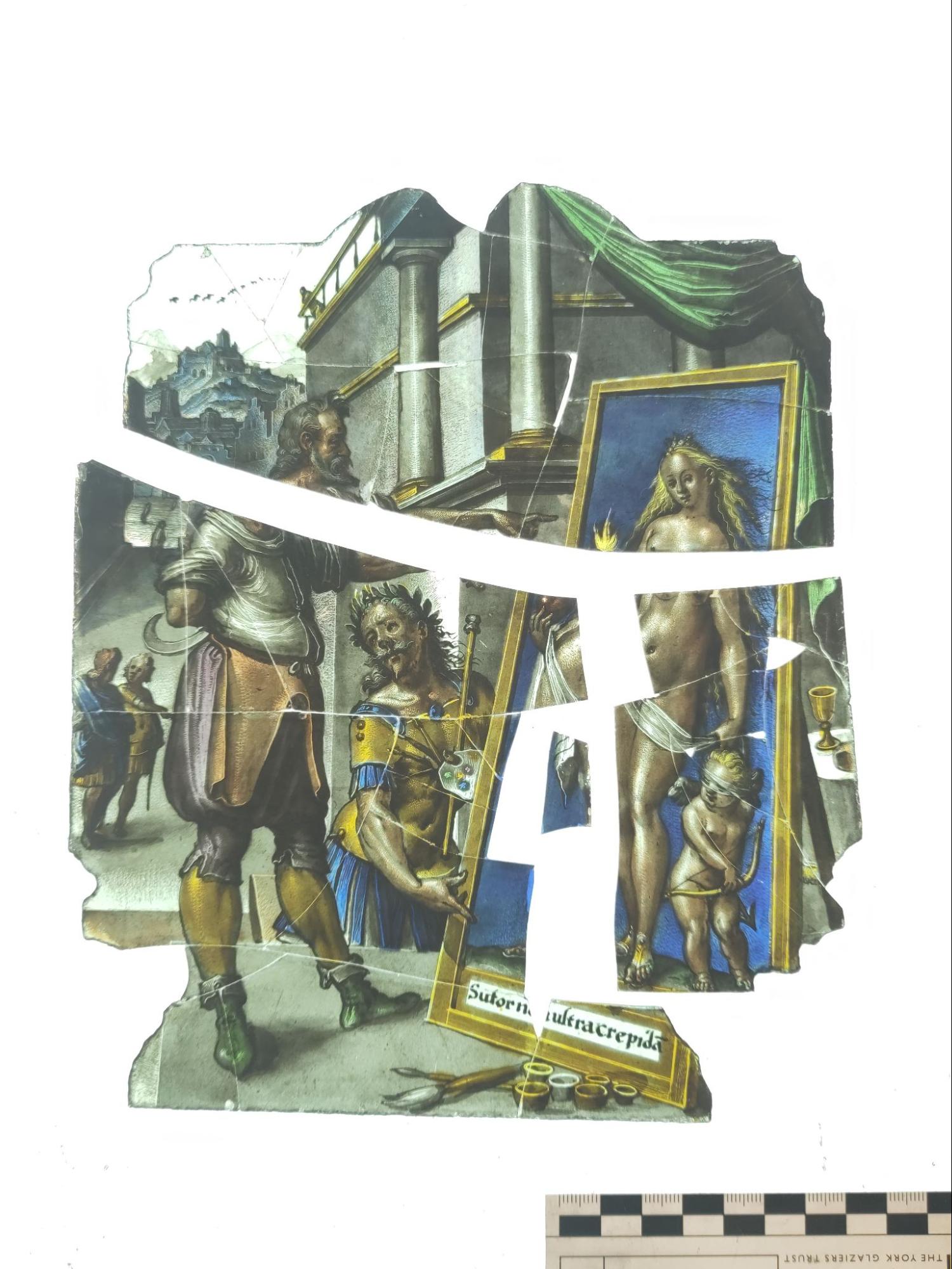
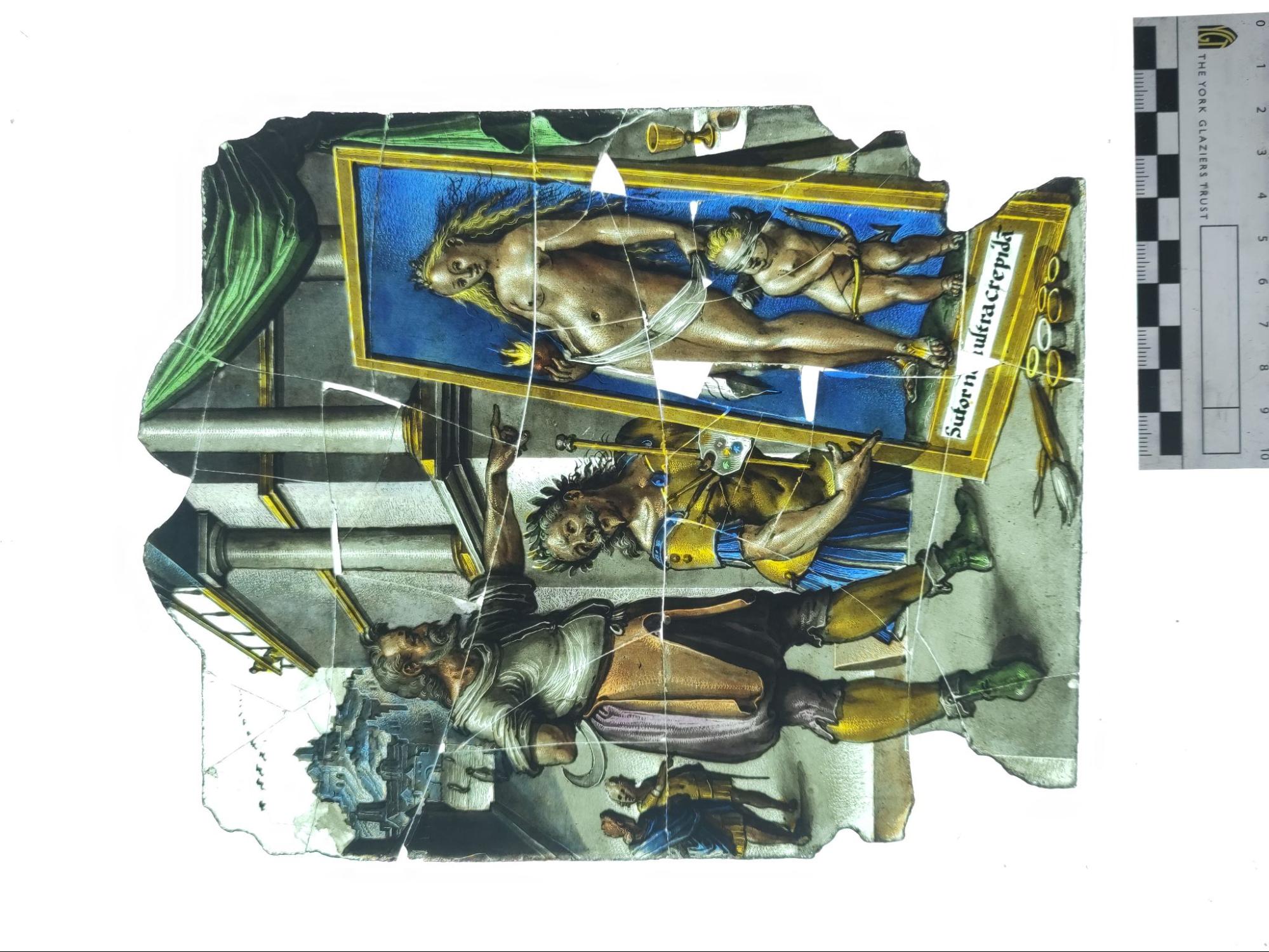
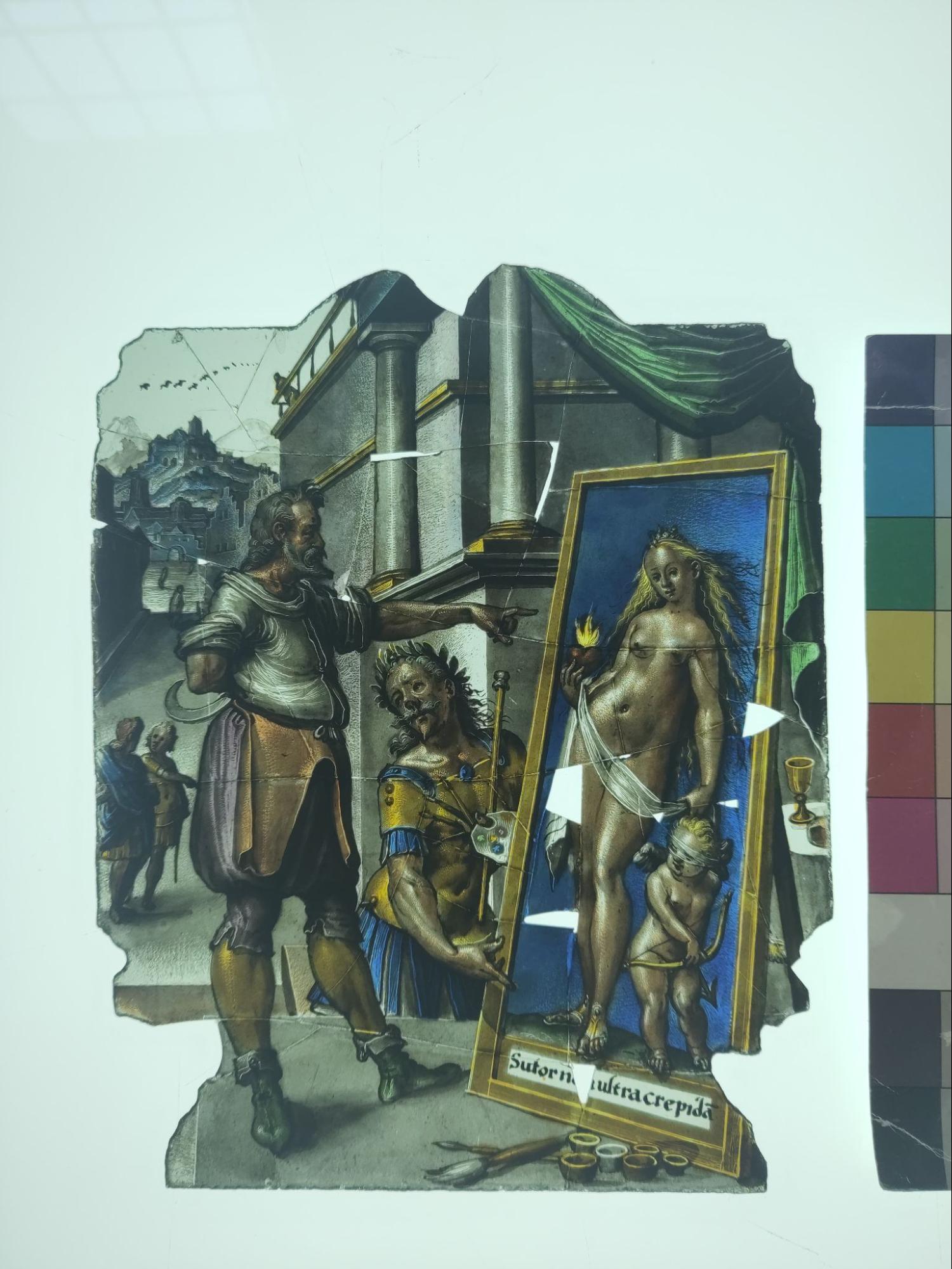
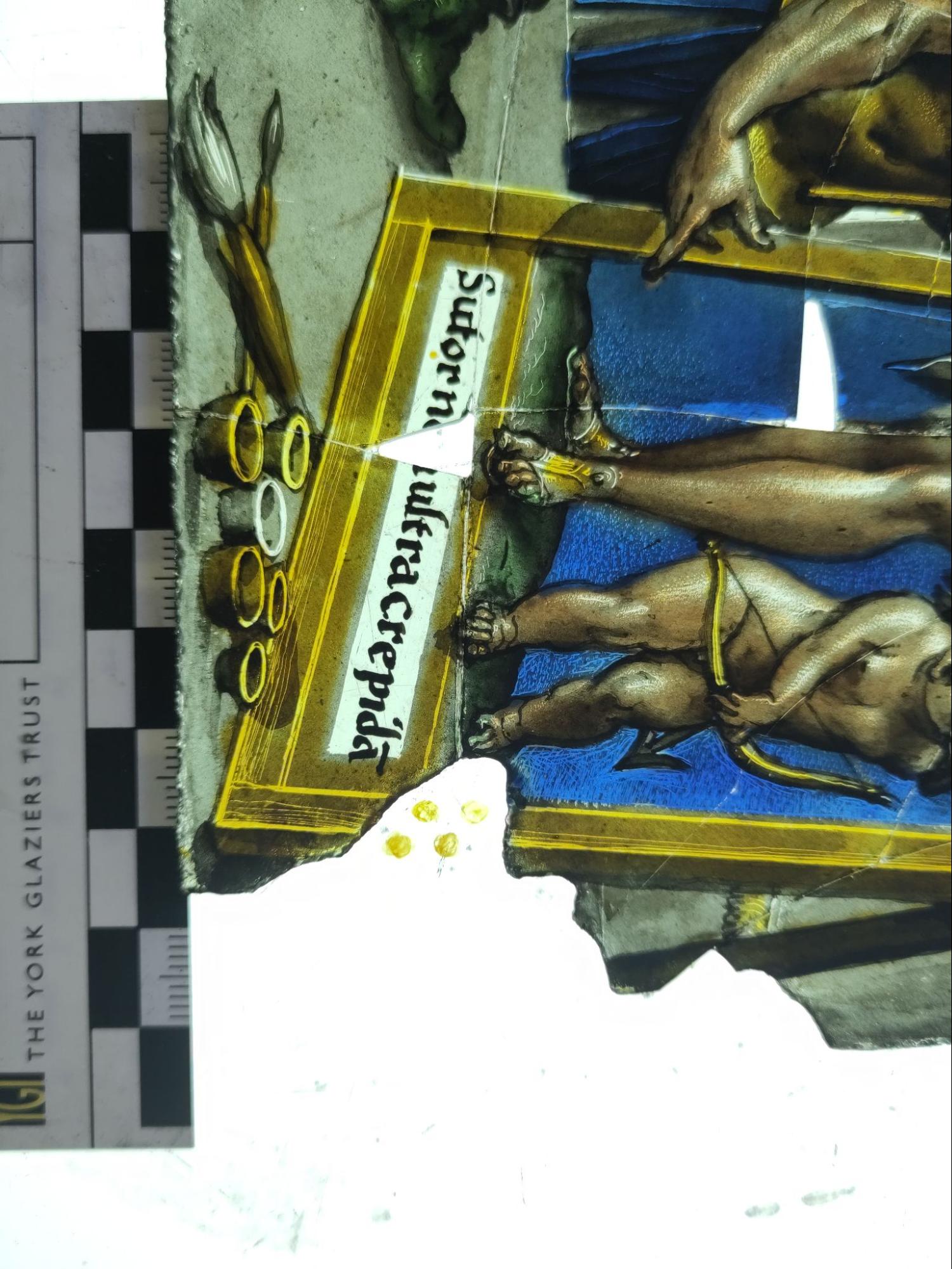
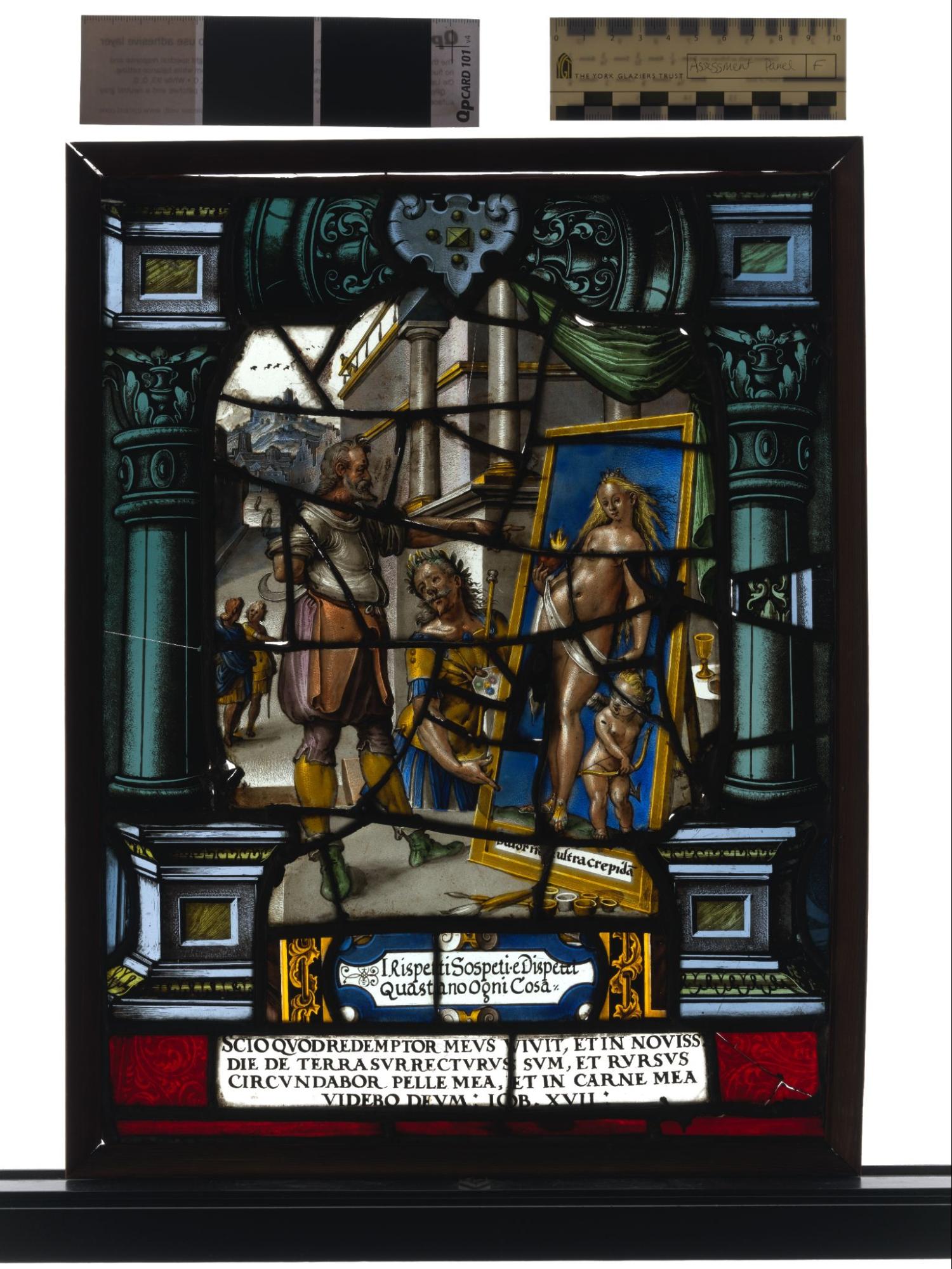
The panel depicts the episode of Apelles and the Cobbler, found in Book 35 of Pliny the Elder's Natural History.[1] It can be identified by the inscription under the painting of a woman and cherub which reads “Sutor ne ultra crepida”which is often translated as ‘Let the cobbler stick to his last’.[2]
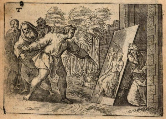
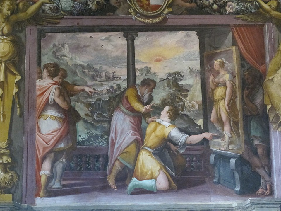
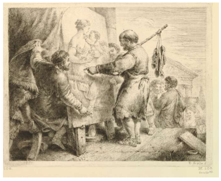
This was an especially popular subject in the 15th to 16th century due to the increased interest in Plato’s writings during the Renaissance period.[3] The treatment of the subject is similar to an engraving by Joos van Vondel (fig 1). While not an exact match by any means, the number of similarities suggests a possible influence between the two images, which could indicate an early 17th century date for the panel. However, other treatments of this subject range from the mid 16th (fig. 2) to late 18th century (fig. 3), so it is difficult to pinpoint an exact date by subject alone.
Figure 1. Joos van den Vondel, Apelles and the Cobbler, published in Den Gulden Winckel der Konstlievende Nederlanders (Amsterdam, 1613), engraving.
Figure 2. Giorgio Vasari, Apelles and the Cobbler, c1541 - 1568. Mural, Casa Vasari, Florence.
Figure 3. Christian Bernhard Rode, Apelles and the Cobbler, 1773. Print, 173mm x 222mm, British Museum, London.
Description | Assessment | |
Glass | Although difficult to assess while the panel is in its frame, the glass is characteristic of C17th glass with little body. Both clear and coloured glass has been used. Flashed blue glass used for the columns on either side. Pot metal red glass has been used for the diaper work sections in the lower corners. | Fair. There is no visible corrosion on either glass surface, with the fire polished surface intact. However, cracks and lacunae are visible throughout the panel. Much of this is likely due to internal pressure within the panel, but it is possible that impact damage has also contributed. Some of the glass is moving within the matrix and is at risk of future loss. |
Vitreous Paint | The paint has been applied in the painterly style associated with C17th century stained glass. The detail and modulation is exceptionally fine, reflecting the talent of the artist. | Good. The paint layer is well preserved. There is no evidence of paint loss or fading, which would indicate unstable paint. Paint issues are restricted to three glass pieces. Two pieces near the bottom of the decorative frame have a microscopic amount of paint cracking. One piece at the top of the panel has two sections of “fried” paint, where the paint has boiled during firing, likely due to too much bonding agent being added. |
Enamels | Enamels have been used both in the figurative section of the panel, and the surrounding border. The appearance of the enamel varies from matt and smooth (pink enamel), to glassy and textured (blue enamel). The artist has varied the thickness of the enamel to achieve different qualities of colour (noticeable in the different treatment of the shoe versus the laurel wreath), suggesting a high level of artistic knowledge. | Good. The enamels are well-preserved. They display no signs of flaking or cracking. |
Putty | Two different types of putty can be seen- black and tan. The putty has not been applied uniformly throughout the panel, it is likely that it was applied to hold loose glass pieces in place. | Poor. The putty has been badly applied throughout, often obscuring some of the surrounding glass. The crumbling tan putty is showing clear signs of degradation, however the black putty looks to be reasonably well-preserved. |
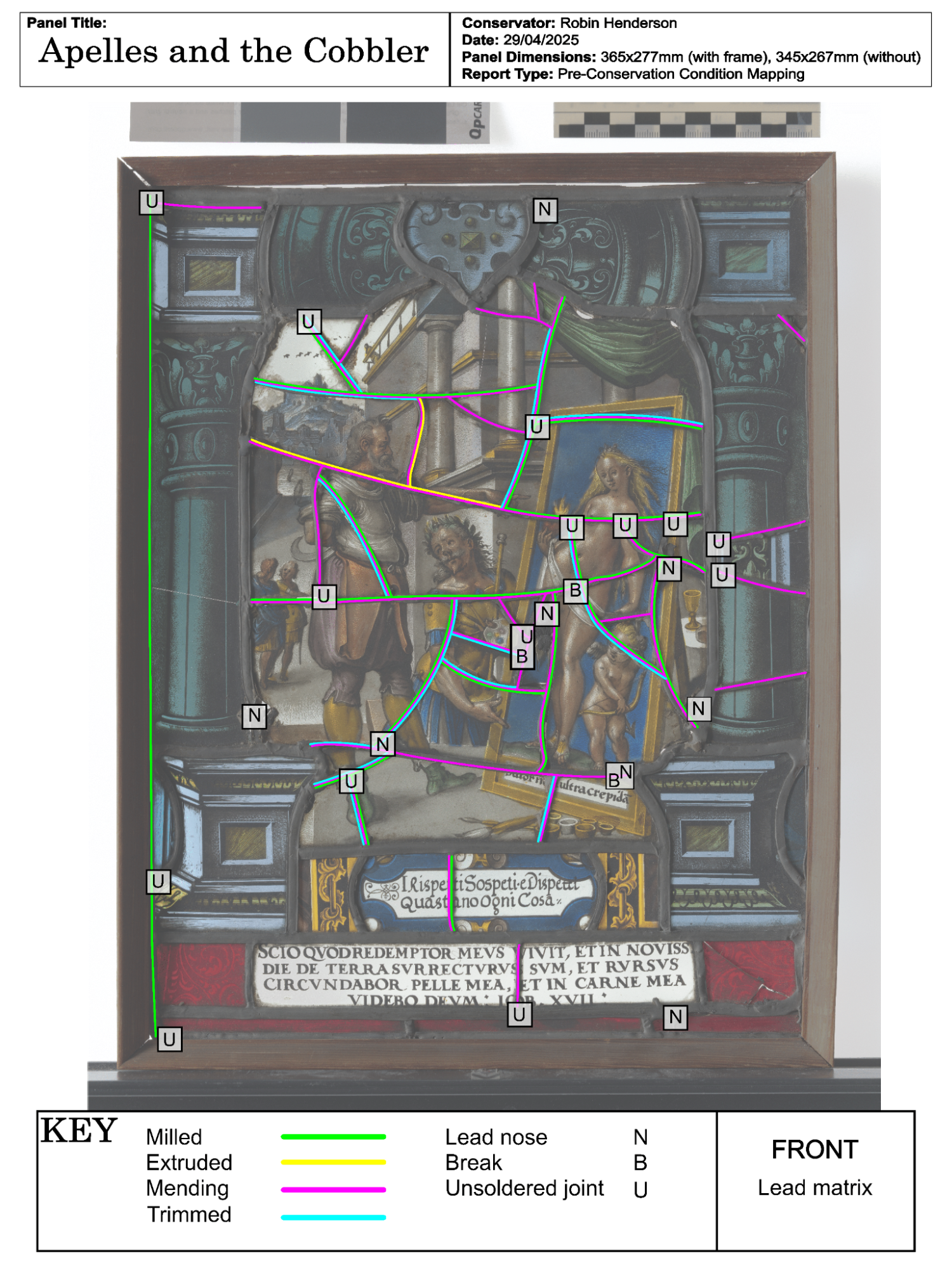
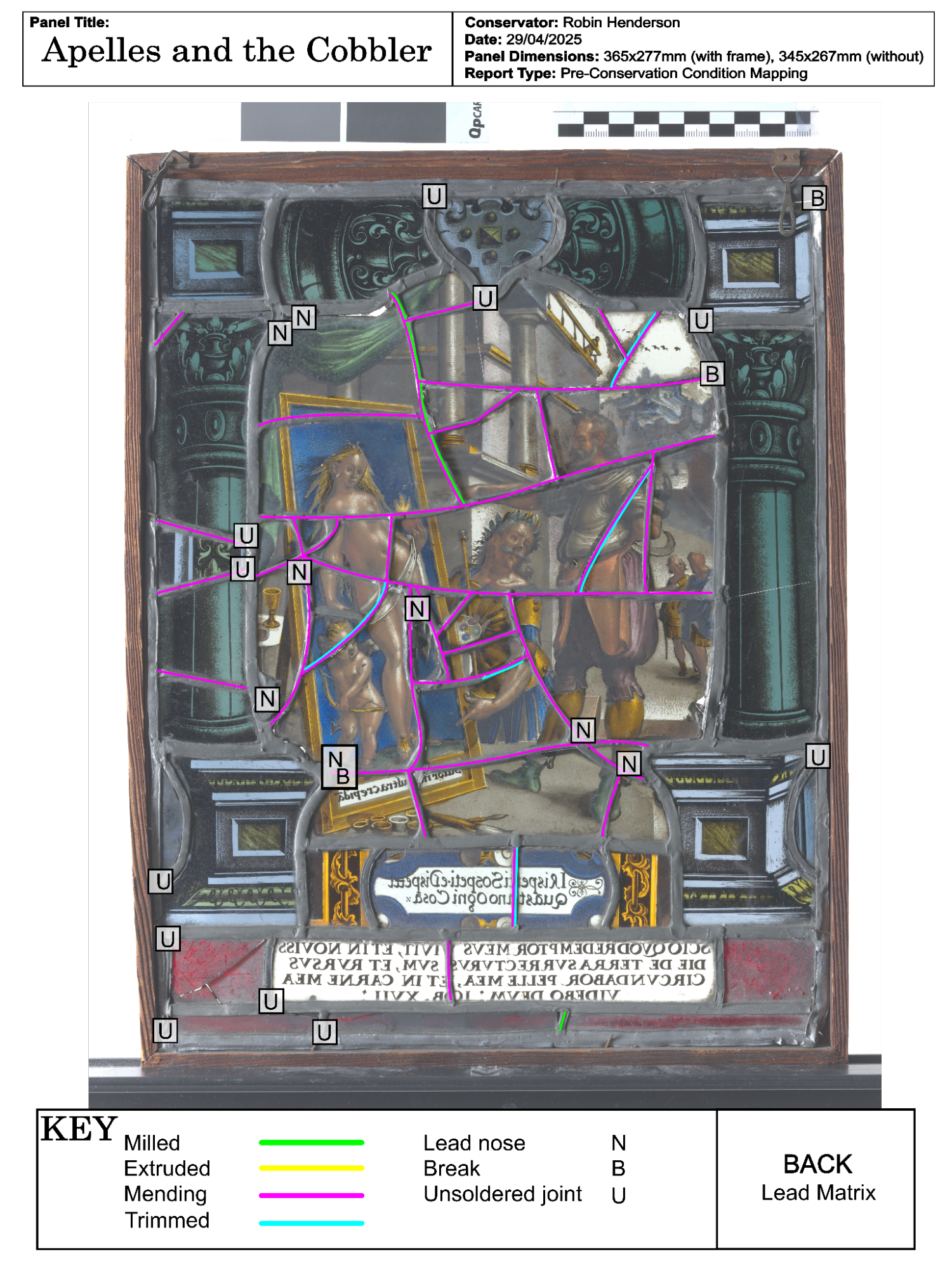
Lead Matrix | Buckling within the panel has exposed some of the mending lead hearts; leads from a variety of periods (milled and extruded) have been used within the panel. This suggests that repairs have occurred over a considerable period of time. The mending leads are exceptionally fine (minimum 1 mm in width) and many have been cut back on the front of the panel, to reduce the visual impact of the leading on the glass. Many of the leads have been soldered from the back of the panel; in some cases the entire back of the came has been covered in solder. This has not been done particularly well and has resulted in solder dripping through, putting further pressure on the glass pieces. The leading in the framing section of the panel is more difficult to assess, but is clearly more regular in size (5mm width) and was likely inserted in one go, either as the panel was originally made, or during a later re-leading. | Poor/Good. The mending leads in the middle of the panel, while of interest from a craft perspective, are generally uneven and exhibit significant deformation. The soldering is also fairly poor. In contrast, the leads from the framing section are in good condition, with little deformation. The lead matrix does not exhibit any signs of lead corrosion, the metallic surface only shows signs of typical oxidation. |
Framing | A wooden frame has been attached to the outside of the panel, allowing the panel to be hung and displayed. This appears to be a picture frame that holds the panel in with pins. A faded sticker has been applied to the top side of the frame. It does not appear to have any historical significance. | Very poor. The frame is not supportive enough for its purpose as the pins that currently secure the panel are coming out. The overall construction is poor as the frame is coming apart at the corners and has significant bowing on the right hand side. |
The following conservation plan has been designed in accordance with the following philosophy:
The treatment goals are as follows:
Problem | Explanation | Possible solutions |
Middle figurative section of panel displays significant buckling. | Caused by the introduction of mending leads, without glass being grozed. Indicates pressure on the glass pieces which is likely to cause further cracking, and possibly material loss. | Remove glass from the lead matrix, bond together, and then return to the panel, removing the current lead matrix from the glass. A full discussion of possible approaches and methods of doing this will be outlined in the Plan of Work below. |
Lacunae throughout | Affects aesthetic values of panel | Cover with lead or fill with putty. Putty is preferable as it is a reversible intervention, but for large lacunae, lead may be preferable. For exceptionally large lacunae, a resin or glass infill may be considered, depending on the specific lacuna’s context. |
The use of thin leads/glass had resulted in a delicate and fragile panel | Makes handling risky for the panel. | Remove unsupportive wooden frame and replace with a brass frame. Brass is a less reactive material that reduces the risk of future corrosion, as well as being suitably sturdy. |
Action | Description and Justification | Time Est. |
Mapping | The panel condition will be fully mapped on front and back. This mapping will record the initial glass condition, dirt, cracks, lacunae, lead came types, lead noses and any other features of interest. All interventions taken on the panel will also be mapped during the process on different layers. | 5 hrs |
Remove panel from wooden frame | This can occur without intervention to the panel itself by removing the framing pins that hold it in place and therefore poses little risk to the panel. Removal will allow the panel to sit directly on the bench, increasing stability during further conservation procedures. | 15 mins |
General cleaning of panel | Firstly the panel will be gently cleaned on both sides using a soft brush and a filtered vacuum. This will remove loose dirt and dust, with minimal risk to the panel. Due to the thinness of the glass, a smoke sponge would not be appropriate, as it applies more pressure to the glass than the brush. The crumbling putty may possibly abrade the glass or paint if moved around the surface during cleaning too much, so a vacuum should be used in conjunction with mechanical cleaning. Because some glass is already mobile within the matrix, an appropriate filter that lets dust and dirt through, but not glass pieces, should be used. | 1 hr |
Removal of old putty | The putty has been poorly applied and exhibits signs of degradation so removal is recommended. While not a reversible intervention, it is retreatable. Much of the current putty seems to have been applied to stabilise the middle section, therefore removing it may help to begin removing unstable glass pieces. Putty will be removed mechanically, using a dental scraper and a scalpel as chemical approaches may leave unwanted residues or water marks on the glass surface. However, depending on the hardness of the putty, it may need softening with compresses before use. Possible compress solutions (deionised water, 50:50 ethanol/water, ethanol & ethyl acetate) will be tested on putty that has been removed from the panel to identify the most appropriate approach, before being used on the panel. Putty residue will be vacuumed off the glass surface, as per the approach used for general panel cleaning. | 1 hrs |
Removal of figurative section | It is expected that some of the unstable glass will be retrieved from the panel when the putty is removed. In that case, the fineness of the leads means that they could gently be pulled back to release the surrounding glass, with little pressure put on the glass-lead structure itself. This is the preferable approach as it minimises risk to the fragile material and leaves the lead matrix largely intact. The mending leads can then be removed from the surrounding matrix; a scalpel would be the ideal tool for this procedure, allowing a significant level of control and precision. If none of the unstable glass is released during the putty removal process, a different approach will be needed. In that case, the left hand column has been identified as a suitable piece to stop out. This will allow the unstable glass to be removed from that side by gently pulling back the leads, again avoiding putting pressure on the fragile centre section. This is an unideal solution as it would require partially dismantling the stable glass surround, but it would allow the unstable glass to be safely retrieved from the panel. If possible the mending lead matrix will be preserved, due to the interesting combination of leads from different eras. It may be necessary to cut part of the inner mending matrix to retrieve some of the pieces, although this will be avoided when possible, due to the risk of putting pressure on the fragile glass. | 5 hrs |
Cleaning of dirt crusts | After the unstable section has been safely removed from the panel, dirt crusts will be manually removed from the extracted glass and the remaining stable glass in the lead matrix. A combination of mechanical and chemical methods will be used. A scalpel will first be used to remove or thin the crusts. If the crusts are stubborn, they can be softened chemically by applying limited amounts of solvents with a swab. If appropriate samples can’t be mechanically removed, tests with deionised water, 50:50 ethanol/water, ethanol & ethyl acetate will be carried out in unobtrusive areas of the panel to identify the best approach, before being applied more widely. | 5 hrs |
Preparing for bonding | Removed glass: Glass pieces will be chemically cleaned along their edges with an ethanol soaked swab. This will remove any residues or dirt traces that may affect the strength of an edge-bond/copper foil application. Glass should then be taped together to prevent it moving during adhesion. If there are any imperfections in the surface, the pieces will be stabilised using dental wax where appropriate. Glass in situ: In situ cracks will be cleaned mechanically with unscented dental floss and an ethanol swab. Glass that is not lying flat already will be manipulated with wooden wedges and dental wax, then taped together, to achieve the correct alignment of the glass before bonding. | 5 hr (in-situ glass) 20 hours (removed glass) |
Edge- bonding the removed glass | A variety of bonding options are available for this panel.[4] The best option will largely depend on the future life of the panel and the conditions it will be expected to encounter. If multiple options are judged suitable for the panel, tests will be carried out on glass of a similar thickness before a final decision is made. My recommendation as a conservator would be to use araldite and store the panel in a stable environment moving forwards, as this would be the only method that preserves both the stability and aesthetic integrity of the panel. Araldite (epoxy resin): This approach will result in a strong adhesive bond that has a similar refractive index to glass. It would be excellent for a panel that will experience regular handling. However epoxy resins are not UV resistant, so it would not be an appropriate material for a panel that is exposed to sunlight as a hanging decoration. It is possible to reverse this bond by swelling it with acetone, however this would be highly undesirable given the thinness of the glass. Silicon: Silicon adhesive results in a strong bond that is UV resistant. It would be appropriate both for handling and display. However it has a different refractive index to glass and therefore can result in an aesthetically unappealing bond. It is very difficult to retreat as it can only be removed mechanically. Paraloid B75: Paraloid B75 results in a weak bond that has a similar refractive index to glass; it would not be suitable for a panel that would undergo significant handling. However it is UV resistant so would be suitable to use as a hanging decoration, as long as it wasn’t exposed to wind pressure. Paraloid B75 is reversible so can easily be retreated. General edge bonding approach: After mixing up the adhesive according to instructions, it will be applied in a manner appropriate to the adhesive. The glass will be edge-bonded from the back to prevent adhesive soaking into the paint layer. While there are enamels on the back, these have a smoother surface so do not run the same risk. After the bonding materials have cured, any excess will be removed with a scalpel. | Making up tests: 5 hours Bonding glass: 10 hours Cleaning glass after bonding: 15 hours |
Cold painting | Cracks through paint and enamels may leave unsightly clear lines through the central pieces after edge-bonding. To restore some of the original historic aesthetic to the piece, cold paint such as acrylic could be applied to the back of the panel. Colour matching tests would be carried out before paint is applied. Acrylic paint can be removed with acetone so this treatment would be completely reversible. | 15 hours |
Bonding the in-situ glass | These pieces should be bonded using the same methods identified for the removed glass. | 5 hours |
Returning the bonded glass to the panel | The amount of bonding required to stabilise the panel will use up a significant chunk of the 100 hours given to this project, therefore I recommend that the final panel glazing should be carried out by another glazier. In addition, the estimated size difference (6mm lengthways, 4mm widthways) caused by removing the lead matrix will result in a challenging glazing situation that would benefit from being carried out by someone with more experience. The next two interventions should be undertaken once the panel is fully glazed, therefore I recommend that they be carried out by the same glazier. | |
Puttying panel | After glazing, coloured linseed putty should be used to fill any small remaining lacuna in the panel, to improve the overall aesthetic result and to stabilise the panel further. For larger lacunae, lead infills may be considered. | - |
Brass- framing | To strengthen the panel further, I suggest that a brass frame should be constructed to give the panel support, to replace the removed wooden frame. | - |
Post- conservation report | Using notes and photo documentation taken throughout the conservation, I will produce a post-conservation report that will record the final conservation decisions made, the materials used and the techniques of their application, up until the panel is handed over to the next conservator. | 20 hours |
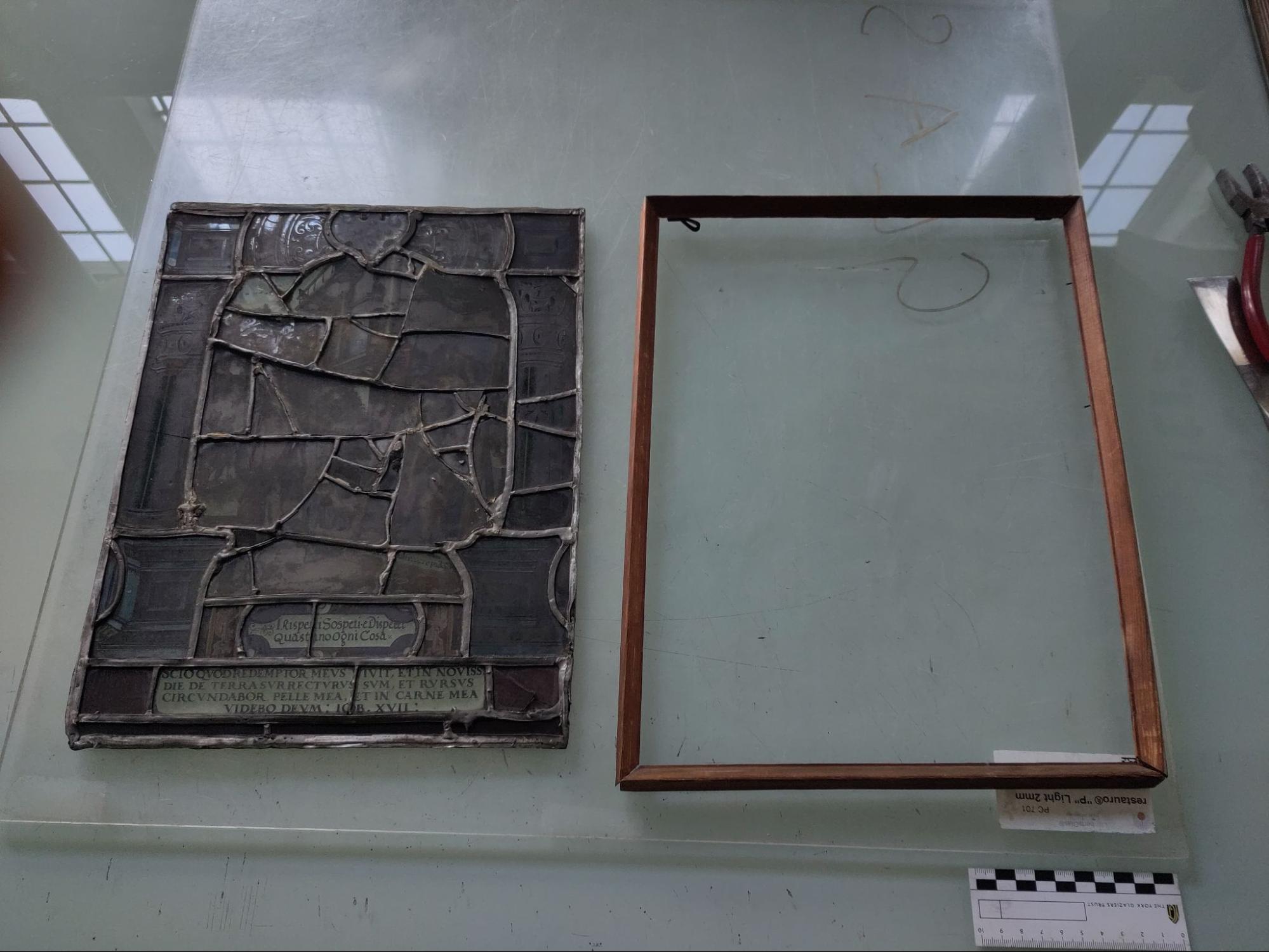
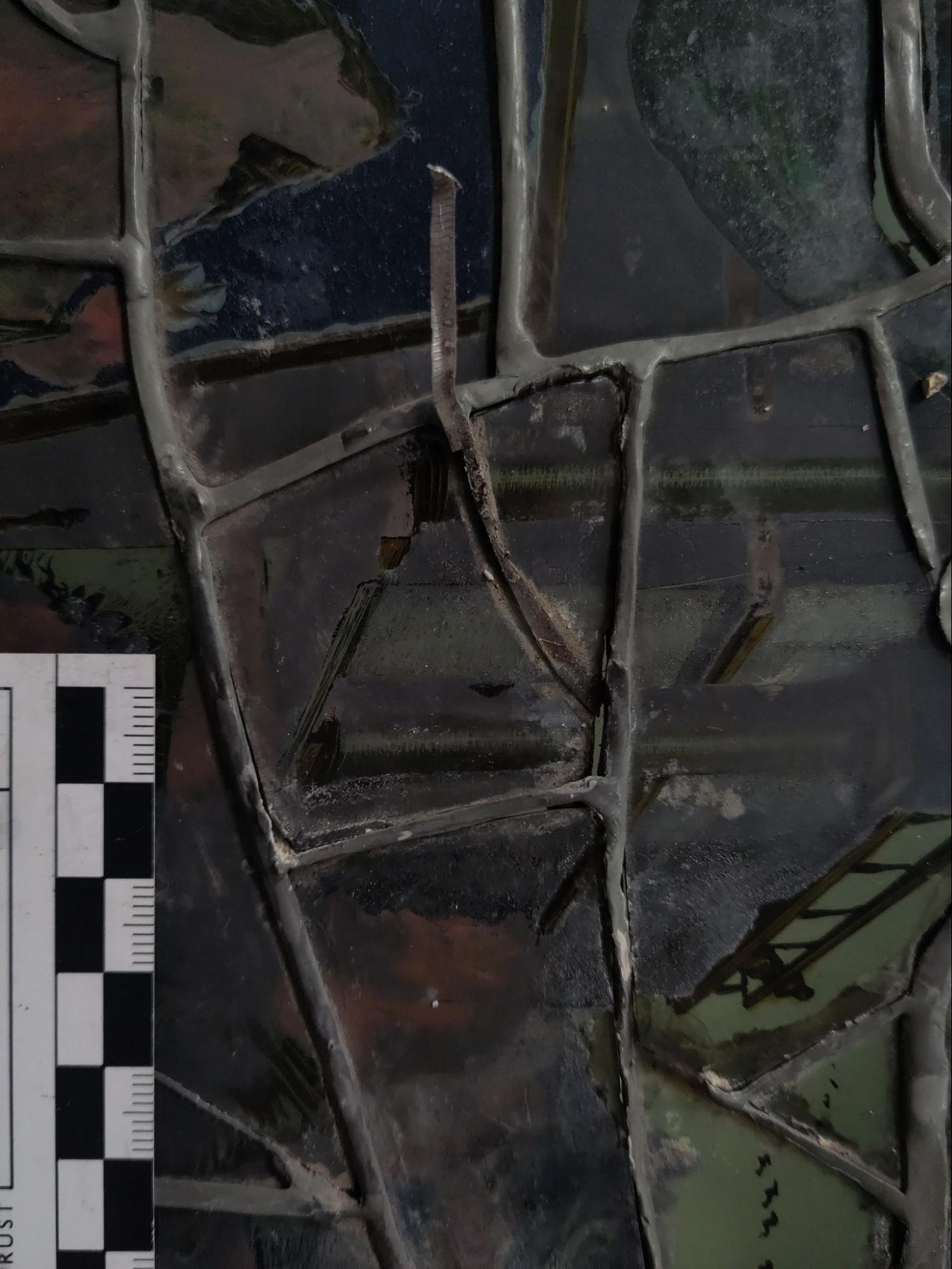
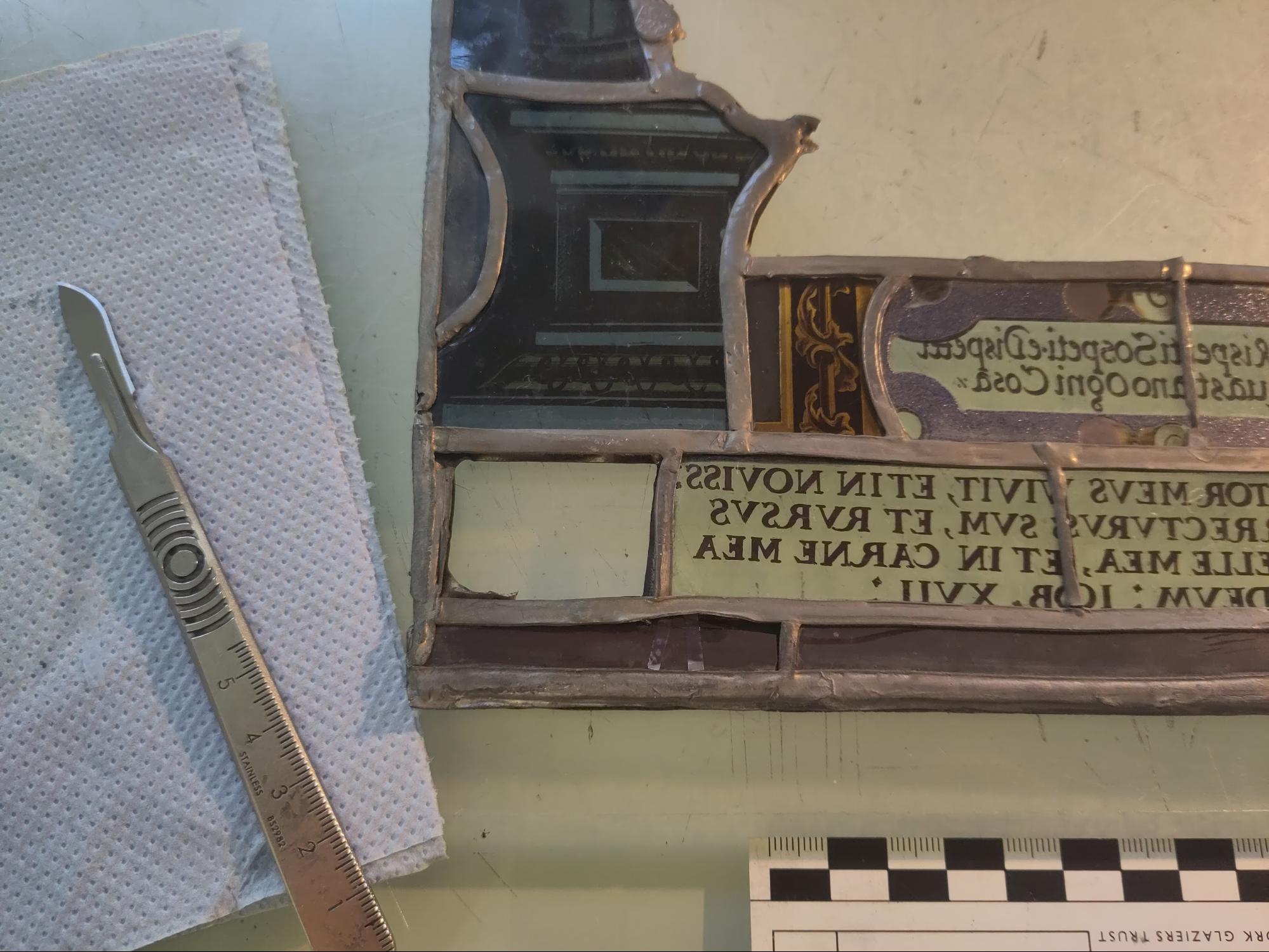
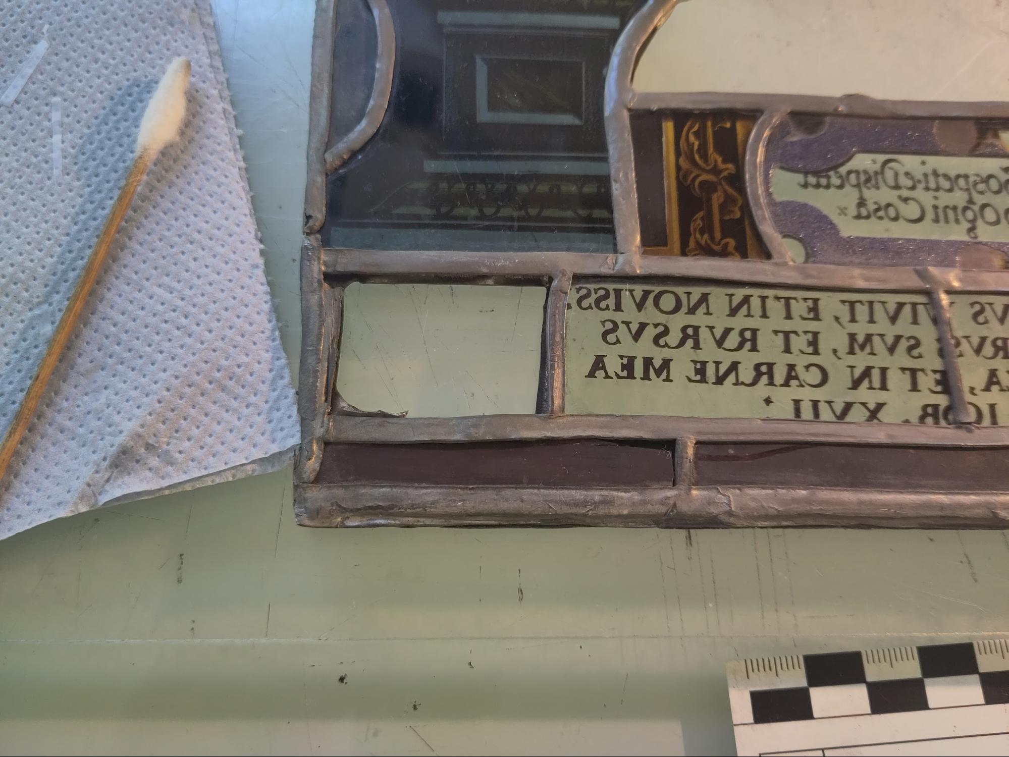
The frame, probably a repurposed picture hanging frame, was removed as per the treatment proposal (fig. 4).[5] Upon removal some damage to the outer lead matrix was observed, due to the pressure of the nails that were holding the panel in the frame (fig. 5).
Figure 4. The panel and frame, after removal.
Figure 5. Damage to the lead matrix, caused by the original framing.
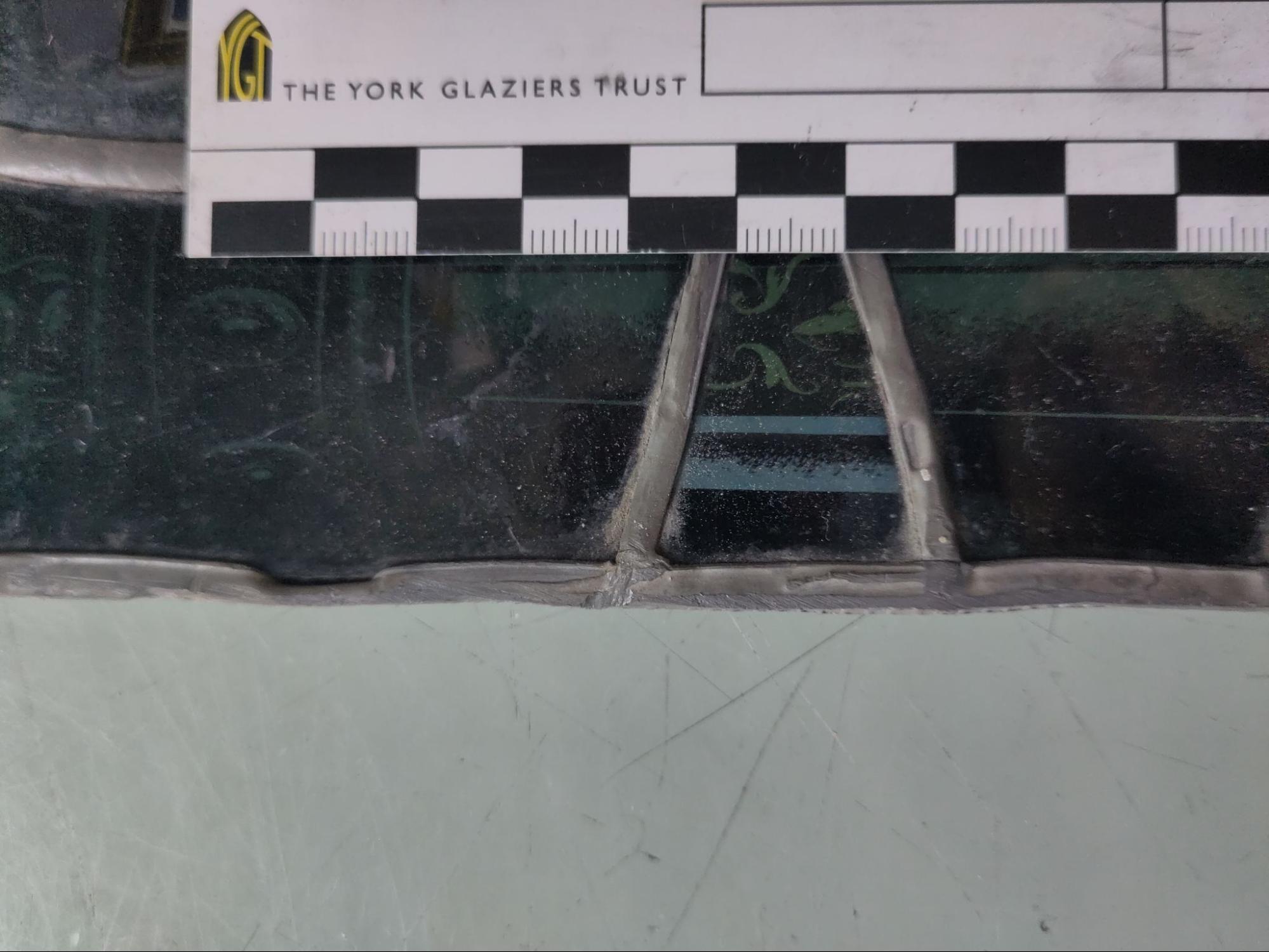
The central glass was removed, as per the treatment proposal.[6] Unfortunately the excessive soldering meant that it was not possible to remove the glass after the removal of the putty, as the excess solder held the glass in place. However, two strap leads were identified during the removal of the putty (fig. 6). These were removed with a scalpel, which allowed enough movement of the glass to begin removing pieces.
Figure 6. A strap lead pulled back to reveal the underlying crack.
In general, cutting the leads at the edge with a scalpel was sufficient to remove each glass piece one by one, alongside manipulation of the lead manually with hands or a putty knife. As the intention was to preserve the lead net structure while removing the glass safely, priority was given to cutting the leads that connected the mending matrix to the main panel matrix. In some cases, it was necessary to cut inner lead connections to safely remove glass, however these were carefully chosen in order to allow the lead net to remain in one piece (fig. 7).
Figure 7. Removed lead net and glass pieces
The lower-right section proved to be particularly difficult due to the large amount of solder present, which reduced flexibility within the section and was difficult to cut. Unfortunately one piece from this section was broken during extraction, this breakage has been documented.[7]
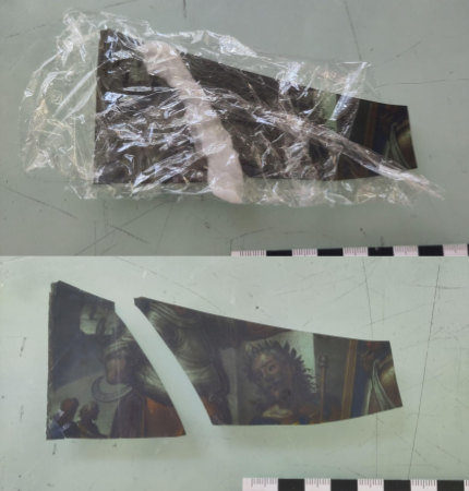
Some glass fragments from the tip of a piece of glass were found during the extraction, the location of where they came from within the panel is mapped.[8] These had broken prior to conservation but had remained trapped in the lead net. While scientific testing is beyond the scope of this project, samples like this would be useful if invasive testing is desired in the future so these have been retained in a small pot for safekeeping.
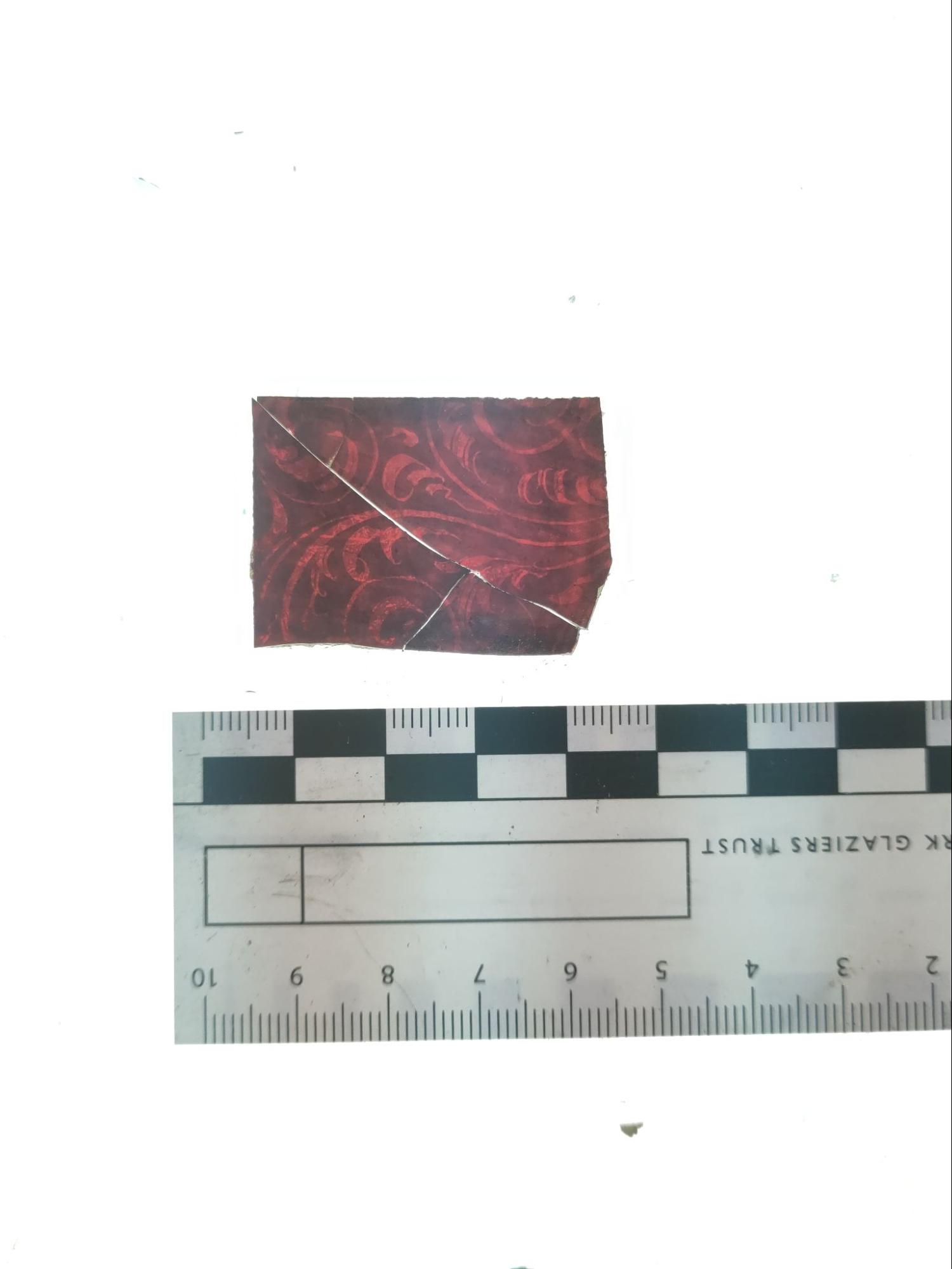
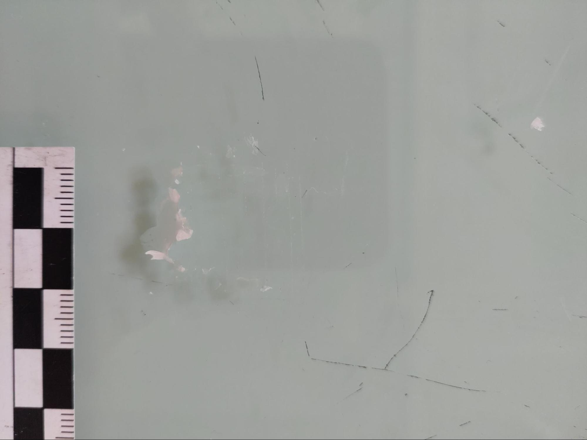
During cleaning, one piece in the lower right corner came loose as it was only held in by dirt and putty (fig 8). It has been edge-bonded and cold painted outside of the lead matrix and will be returned to the panel during the later glazing stage.
Figure 8: The border piece after extraction, prior to cleaning and edge-bonding.
Loose dirt and debris was removed from the panel at the start of the cleaning process using a soft brush and a vacuum, as per the treatment proposal.[9] Aida fabric was found to be a suitable filter for the vacuum nozzle, as it let fine particles through but nothing larger than 1-2 mm. For adhered dirt and debris, cleaning was mostly done mechanically with a scalpel. Chemical cleaning was also used for specific cases, as detailed in the sections below.
When deciding on the appropriate level of cleaning, aesthetic considerations were factored in, but priority was always given to the preservation of original materials.
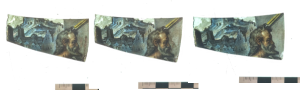
Dirt crusts were found over the entire panel surface. These varied in thickness and in colour from a reddish brown to dark black. In general, the thick crusts were gritty and crumbly. They were easily removed using a scalpel, with any residues removed using a swab and deionised water. Thinner crusts were more challenging to clean. In some areas these crusts were only distinguishable by a slight colour difference that did not relate to the paint layers. Compresses of deionised water, 50:50 deionised water and ethanol, ethanol and ethyl acetate were trialed towards the bottom of the panel. In general a compress of 50:50 deionised water and ethanol was found to be suitable for softening crusts so that they could be removed mechanically. In some cases with particularly persistent crusts, pure ethanol was used instead. It was not possible to fully remove the very thin crusts, as the amount of mechanical cleaning needed could have caused possible damage to the paint layer. Instead, the crusts were thinned out at the edges to minimise unsightly ‘lines’ on the paint layer (fig. 9).
Figure 9. Before, during and after cleaning. The middle image was taken after the thicker dirt crust on the left had been removed, the difference between the clean surface and the thin dirt crust is evident. In the third image, the thin crust has been thinned out to improve the aesthetic outcome of cleaning.
When cleaning dirt crusts from the glass that remained in the lead matrix, light pinprick corrosion was visible on the fire-polished surface under the crusts. This illustrates how the hydrophilic nature of organic matter can lead to corrosion of glass.[10]
Two types of putty were identified on the panel surface. One of them was a light tan colour and crumbly in texture, occasionally with some darkening on the outside. The other was a dark black with a solid gritty texture. To identify a suitable approach for cleaning, samples of each were removed mechanically from the panel with a scalpel before being immersed for 1 hour in different solvents : deionised water, 50:50 deionised water and ethanol, ethanol and ethyl acetate. The results are summarised in the following table.
Solvent | Effect on Tan Putty | Effect on Black Putty |
Deionised water | Fell apart | Some softening |
50:50 deionised water and ethanol, | Fell apart | Some softening |
Ethanol | Softened | Putty had begun to fall apart |
Ethyl acetate | No change | No change |
Based on these results, deionised water was used as solvent for tan putty and ethanol was used as a solvent for black putty. In general however, mechanical cleaning with a scalpel was generally sufficient to remove putty residue from the glass; compresses were only used for particularly stubborn areas.
During cleaning it became apparent that the flesh-tone enamel was more unstable than it previously appeared during the initial condition assessment. Aside from a slight thinning of a small section, there was no significant impact on the enamel during cleaning. Since the enamel was stable enough to withstand general handling it was not considered necessary to stabilise with a consolidant such as Paraloid-B72.
During cleaning, it also became apparent that some darkening on the back of the panel which initially looked like a dirt crust was actually a damaged vitreous paint layer. This layer has been applied to achieve an effect of shadow. It was possibly fired along with the enamels on the back side of the glass; as vitreous paint generally has a higher firing temperature than enamels it was likely therefore underfired, which is causing the current instability. Since the degradation was severe and was likely to continue, the decision was made to stabilise the remaining paint with 7% Paraloid-B72 in an acetone solution, applied with a soft brush.[11]
Upon agreement with the owner, the epoxy resin Araldite was used for all edge-bonding, as per the reasoning in the treatment proposal.[12] The adhesive was mixed an hour before use to increase viscosity - this prevented the possibility of adhesive soaking into the paint layers on the glass. The methods of aligning the broken glass together varied depending on the location of the glass, this is elaborated on in the relevant sections below. Once the glass was correctly aligned, small strips of tape were added for further stabilisation. Dots of clear araldite were applied with a surgical needle. The adhesive was left to cure overnight before the excess, along with the tape, was removed. This length of curing time allowed the adhesive to develop enough strength to hold the pieces together without external support, but left some flexibility for ease of removal. Removing the excess adhesive and tape was done mechanically with a scalpel, with any residue removed with a ethanol soaked swab.
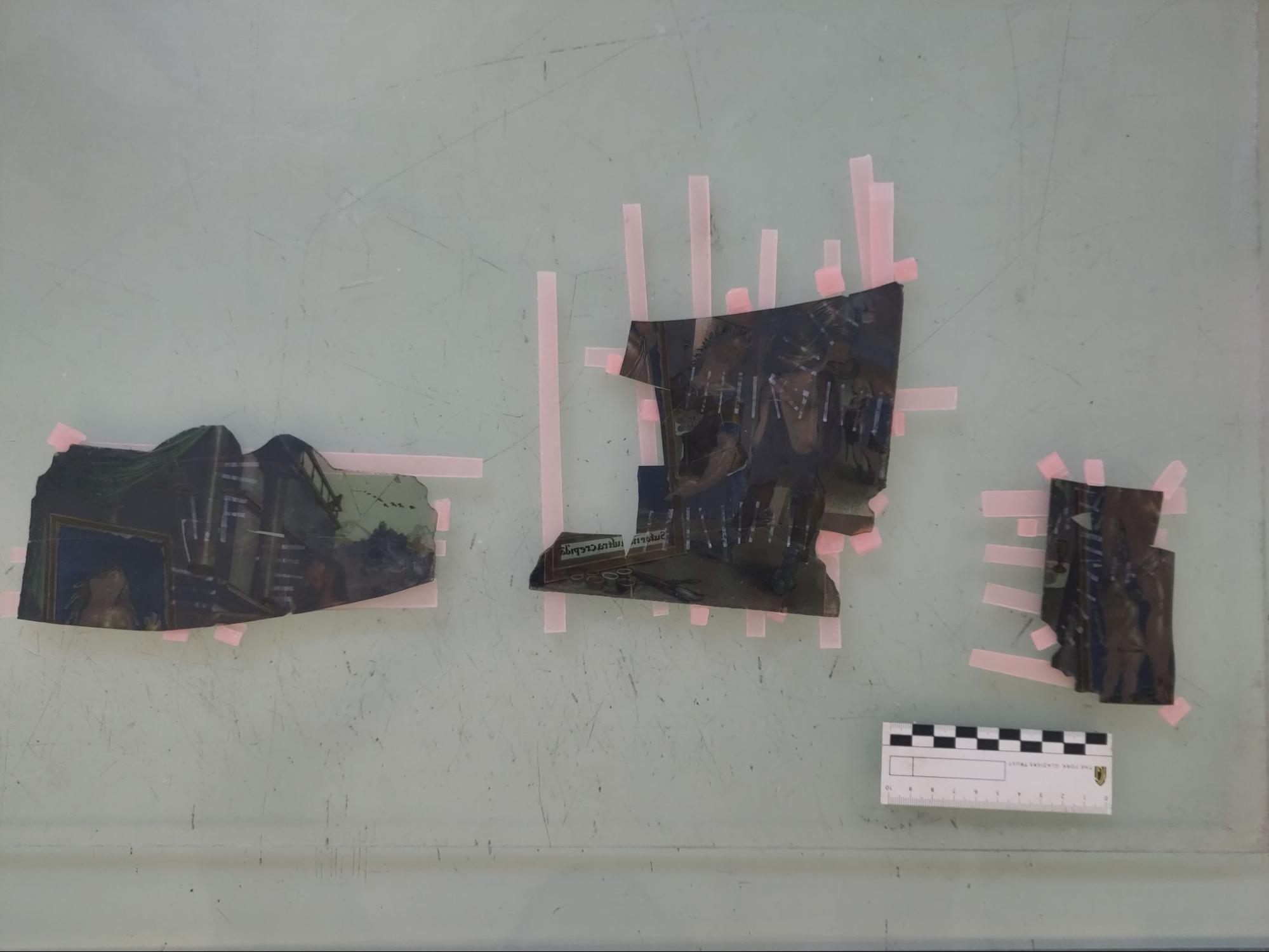
Because of the size of the central figurative section and the number of glass pieces involved, the edge-bonding for the extracted glass pieces was carried out in three separate stages. This involved bonding small sections of the panel together, then bonding the small sections into large sections, and lastly bonding the large sections into the full piece. This approach allowed for a greater level of accuracy when lining up the glass pieces and therefore a better quality of bonding throughout the piece. Pieces were grouped together so that they could be easily aligned through matching up the paintwork, as well as forming roughly rectangular shapes so that further edge-bonding stages would be straightforward. The stages of edge-bonding are visually recorded in figures 10-12.
Figure 10. Sectioning for the first round of edge-bonding.
Figure 11. Sectioning for the second round of edge-bonding.
Figure 12: The panel after edge-bonding.
To align the glass, it was first placed on wax strips, which were arranged perpendicularly to the line of edge-bonding (fig. 13). If further stabilisation or alignment was needed, more wax was added in the form of strips or wedges. In general, adhesive was applied to the back of the glass, as per the treatment proposal.[13]
Figure 13. Aligning pieces for edge-bonding.
For the first round of stabilisation, I avoided applying Araldite to the pink enamel surface as I had concerns about its stability, so for pieces where a crack had formed through the pink enamel, I applied adhesive to the painted side instead. Despite my attempts to the contrary, some Araldite did drip through and ended up on the pink enamel. I found that when removing this excess, the pink enamel was in fact stable enough for the Araldite to be safely removed mechanically. As it was noticeably quicker to remove excess adhesive from the non-painted side of the piece, in further rounds of edge-bonding all pieces were bonded from the back.
There was one instance where I was unhappy with the alignment of a particular bond so reversed the Araldite bond using an acetone compress (fig. 14). While acetone can cause swelling in epoxy resins which is a possible risk to the glass, in this case the break was straight across and therefore any swelling of the bond would have had a negligible risk to the glass itself.
Figure 14. Reversing an araldite bond using an acetone compress.
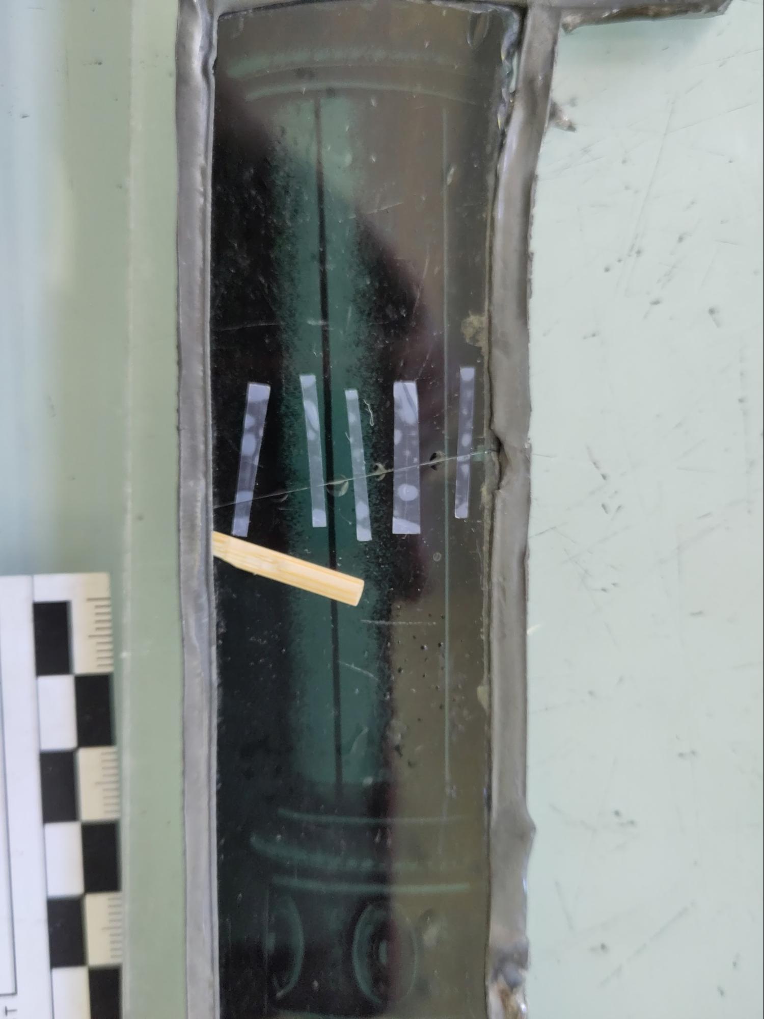
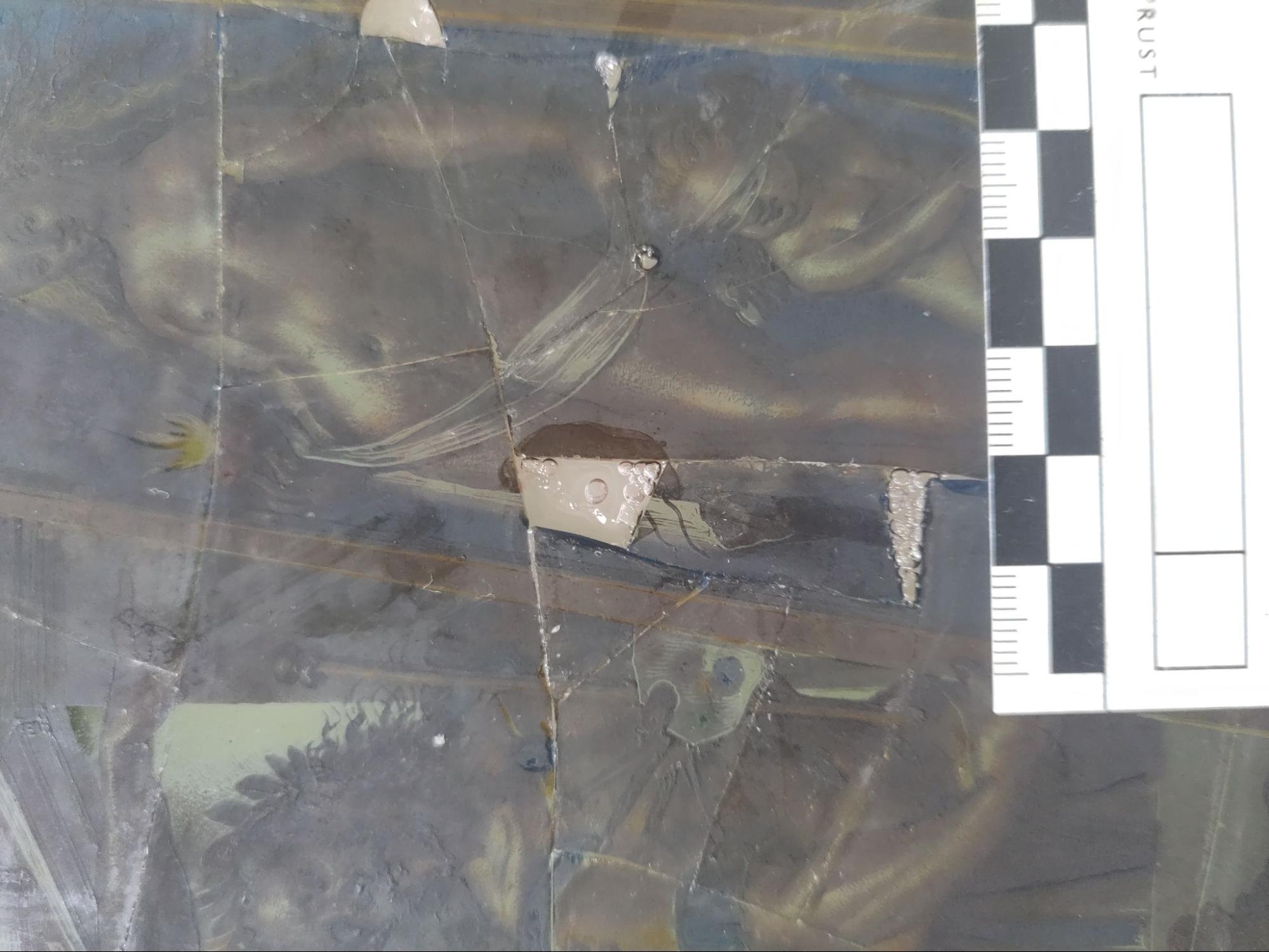
To align the in-situ glass, different methods were used for each break. The most challenging in-situ break was found at the bottom of the panel where a very small sliver of glass had broken off. While it would have been possible to leave it as the glass and lead held it roughly in place, the fact that it was very mobile within its position suggested that it was at high risk of loss if left untreated.
To stabilise it, the surrounding lead flange was gently pushed back with a putty knife, and the loose glass was fully removed and cleaned with a scalpel and a ethanol swab. The area the glass came from was also similarly cleaned as much as possible, using a dental scraper in addition to the swab and scalpel used before. The glass was then returned, and held loosely in place with small strips of tape (fig. 15). It was not possible to align the glass as precisely as in other locations, due its location under the lead flange; however the aesthetic impact of this was minimal due to the small size and unobtrusive location of the broken glass. After being bonded and the join cleaned, the lead flange was gently returned to its original location with the putty knife (fig. 16).
Figure 15. The break immediately after the application of Araldite.
Figure 16. The break after edge-bonding and cleaning, with the lead smoothed down.
The second in-situ crack was far more straightforward and the broken glass remained within the lead matrix. To stabilise it in situ, wooden wedges were constructed from a wooden skewer using a scalpel, and used to align the broken glass (fig. 17).
Figure 17. Edge-bonding within the lead matrix, using wooden wedges and tape.
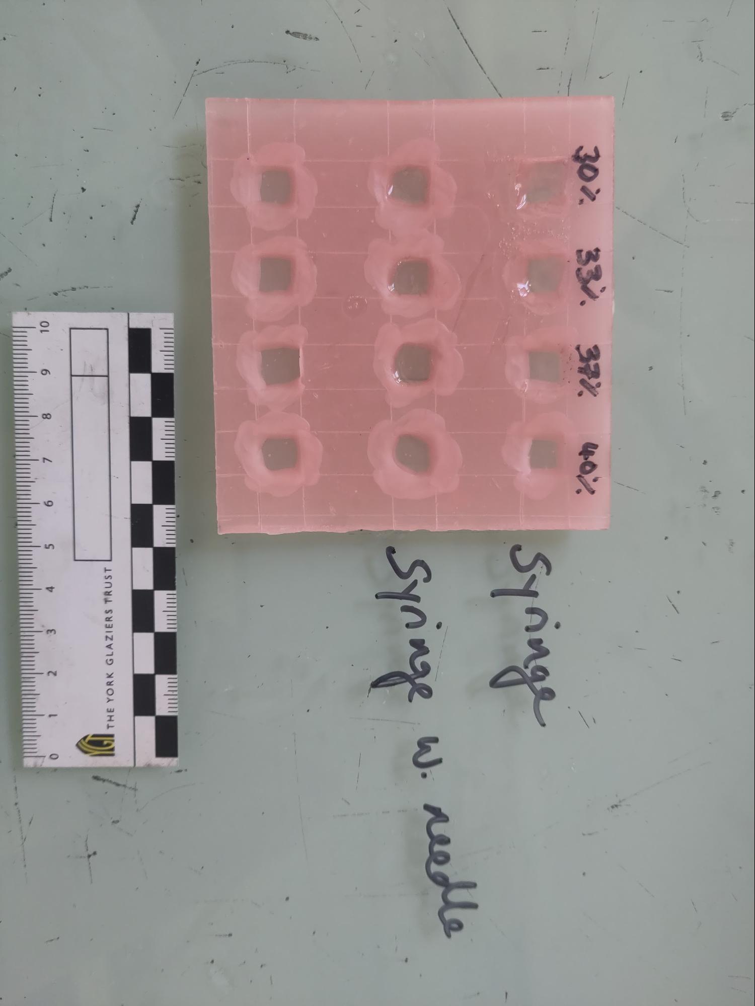
It was judged necessary to fill the gaps within the central section of glass, both for stability and aesthetic purposes. Because of the small size of these gaps, glass infills would have been incredibly difficult to insert, therefore a poured infill was seen to be a more appropriate choice. Because an infill would have been a new introduction to the historic material, retreatability was paramount in identifying a suitable infill material. For this reason Paraloid-B72 was chosen over Araldite. As I had not worked with Paraloid-B72 as an infill material before, I conducted tests to establish the most appropriate formulation and method of application (fig. 18).
Figure 18. Testing Paraloid-B72 infills.
After making up a double layered piece of dental wax with 1cm x 1cm sealed holes, I then applied Paraloid with a syringe and a syringe with needle. The syringe was very difficult to control, but adding a needle allowed for the solution to be carefully dripped in with greater accuracy. Since this seemed to work well, no further methods were considered. A 30%-40% formulation of Paraloid B72 is usually used for casting,[14] so I experimented with percentages between these two values. The 40% had less bubbles during the initial application and was easier to apply.
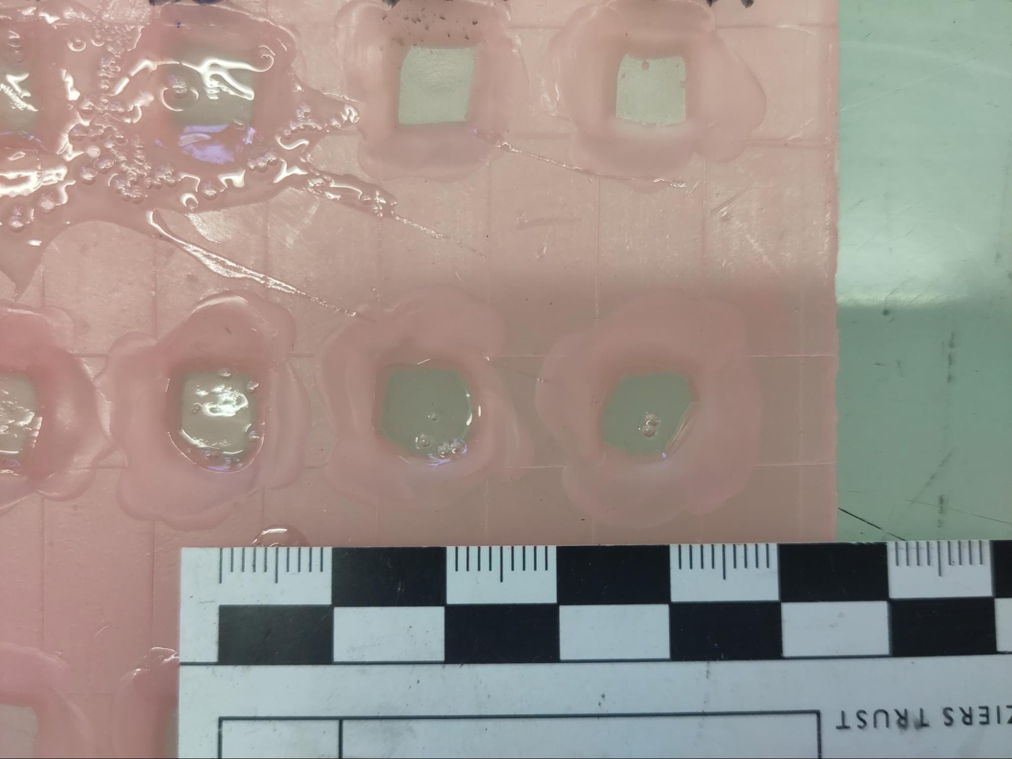
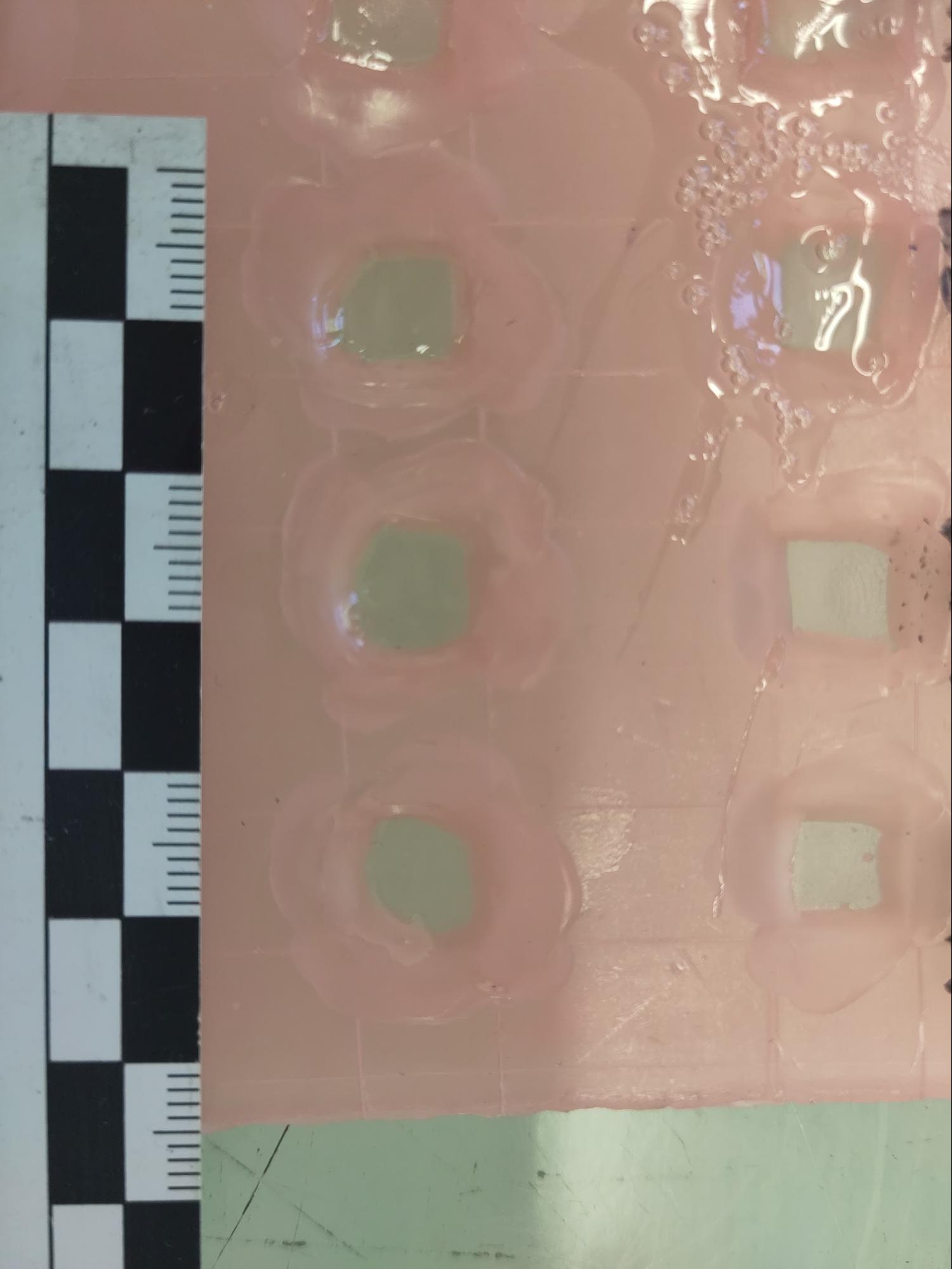
After the Paraloid-B72 tests had set overnight, it became apparent that some bubbling had occurred during the setting stage, likely due to the evaporation process involved in hardening (fig. 19). Only a few bubbles appeared in each and were easily removed using a brush dipped in acetone (fig. 20). There was not a remarkable difference in the final results for each test, so the 40% solution was chosen based on its ease of application.
Figure 19. The paraloid infills after setting. A few small bubbles can be seen.
Figure 20. The paraloid infills after setting. The bubbles have been removed with acetone.
A great challenge when applying infills to this particular panel was the warping of the glass piece, as well as the fragility of the thin glass and therefore thin edge-bonds. While trying to gently press the glass on to dental wax to create a contained space for an infill, one of the bonds became weak and flexible. While it did not give way entirely, it indicated that a different approach was needed to prepare the panel for infills.
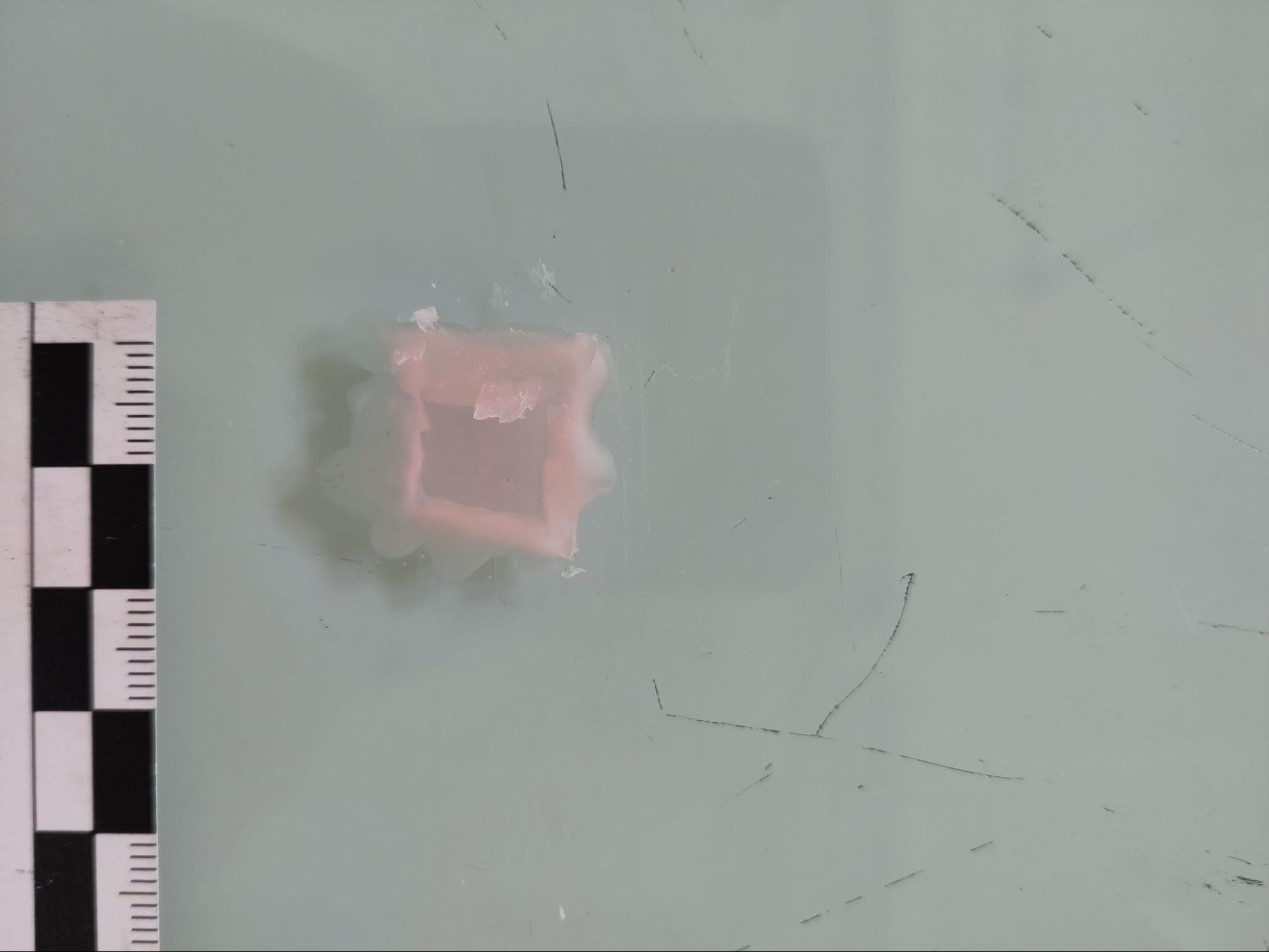
Melting the wax onto the panel from the back meant that no pressure would be applied, and would ensure a liquid-tight seal. To test this method, a small square of wax was applied to the glass worktop (fig. 21) and the edges carefully melted with a soldering iron set to the lowest possible setting (50℃). It was possible to accomplish this by only touching the wax, not the glass surface. This approach minimised any risk to the glass due to heat stress, therefore it was judged suitable for use on historic material. To remove the wax, a scalpel was used to peel the test piece off the surface (fig. 22). This entirely removed the middle section of the wax, but left a residue around the outside. This could be largely removed mechanically with the scalpel, with any last residue removed using a swab soaked in white spirit.
Figure 21. Testing wax infill backing on glass.
Figure 22. Wax infill backing after mechanical removal, prior to chemical cleaning.
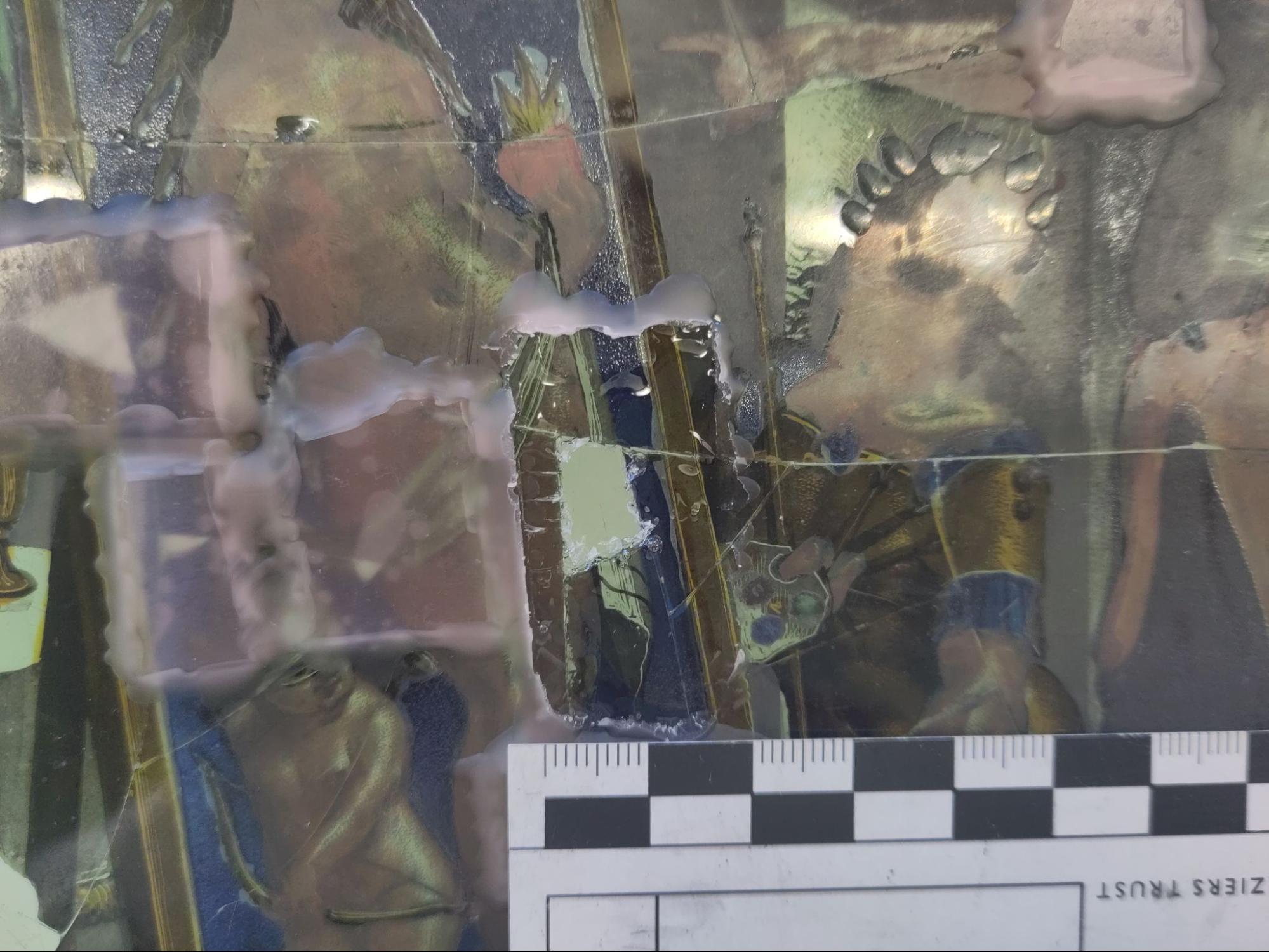
Based on these trials, small wax squares were applied on the back of the panel using the method described above. They were gently pressed down to seal in the infill area. These were then filled from the front with a 40% Paraloid-B72 solution and left to set overnight. Unfortunately, during application to the panel, the Paraloid-B72 infills exhibited markedly different behaviours from the test samples, resulting in significant bubbling (fig. 23). While this could be removed with acetone, the large size of the bubbles resulted in a rough surface finish, making it incredibly challenging to achieve the smooth, level finish desired. The mixture also shrank significantly in volume so needed repeated fillings, all of which resulted in the same problems.
Figure 23. Bubbling of Paraloid-B72 infills after setting.
Upon turning the panel, the wax squares had completely filled with Paraloid-B72. This was frustrating but ultimately reversible; however on removing the wax squares the Paraloid-B72 infills came completely out with the wax (fig. 24). This was due to the fact that the Paraloid-B72 trapped under the wax had not set properly as the acetone could not evaporate; instead it formed a sticky mixture that stuck to the wax on removal.
Figure 24. The Paraloid-B72 infill has been almost completely removed with the wax.
At this point I had to decide whether or not to reattempt the infills and I was roughly 80 hours into a 100 hour project. Since I still had cold-painting, report writing and mapping to finish, not to mention removing the failed infills, I judged that there was not enough time to make another attempt in the parameters of this project. Reflecting on the failure of this intervention, I believe my initial testing failed because I did not accurately mimic the panel conditions in terms of depth and shape. Another failure point was the sealing of the glass gaps, which was ineffective. One possible method of improving the seal would have been to heat the entire wax square before application, to ensure it made a firm seal with the glass around the infill.
Removal of the failed infills was straightforward and the panel was successfully returned to its prior condition. Wax and Paraloid-B72 were largely removed mechanically with a scalpel. Remaining Paraloid-B72 residues were removed with a swab soaked in acetone, wax residues were removed with white spirit.
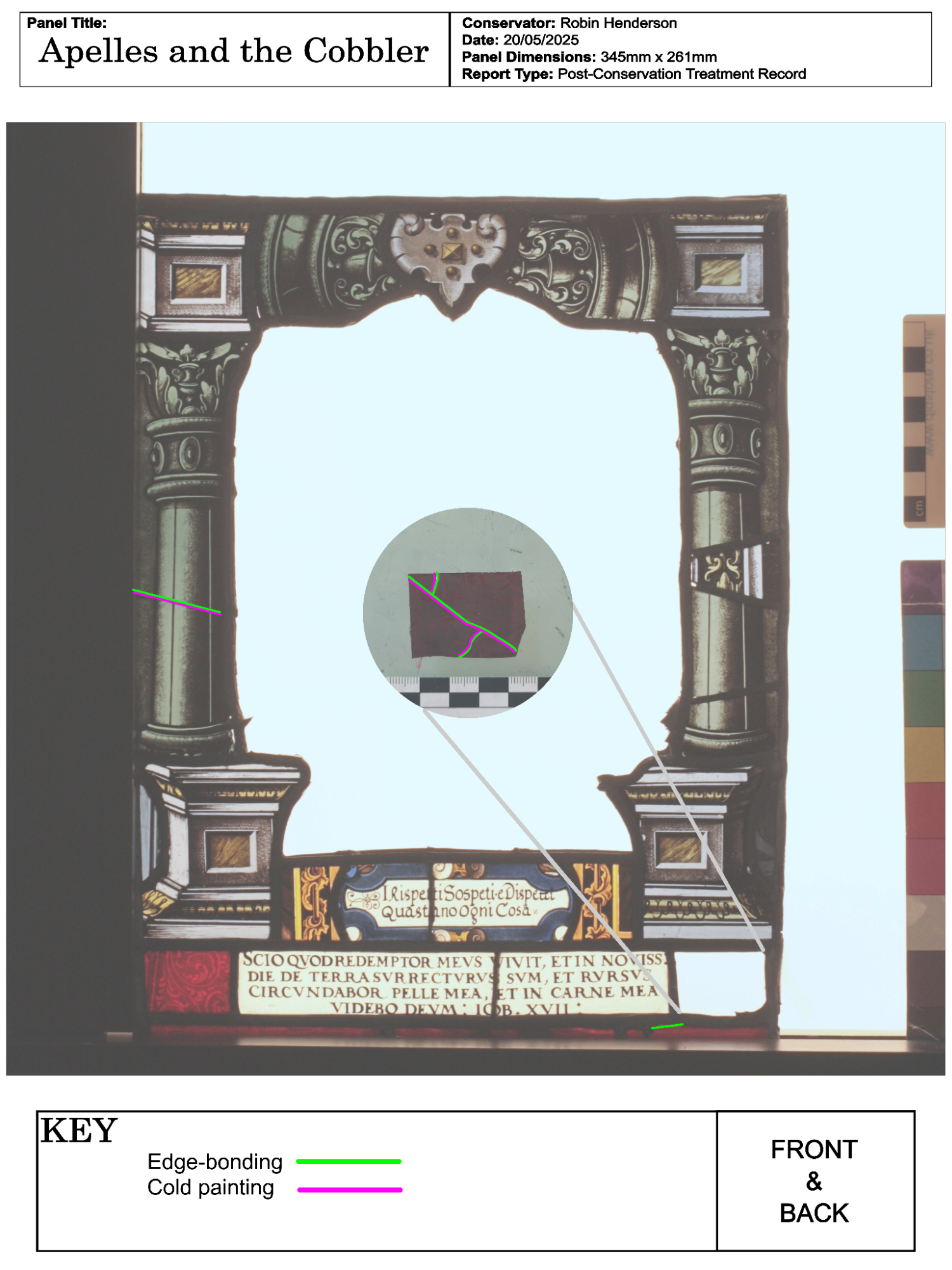
To improve the overall aesthetic appearance, cold painting was applied over cracks in the enamel and paint layers (fig. 25). Initially I had hoped to do all cold-painting on the back to ensure a clear distinction between the original paint/enamels and the introduced cold paint. However, it became apparent that filling gaps in the front vitreous paint layer from the back resulted in a poor aesthetic appearance due to parallax. Therefore I switched to cold-painting the “grisaille” on the front, while the cold-painted “enamels” were painted from the back. I also found that the flashed red piece needed painting from the front, again due to parallax.
Figure 25: The central section after cold painting.
Acrylic paint, thinned with water when needed, was used for all cold painting. A summary of the colours used to replicate certains aspects of the glass/paint/enamel, including estimated percentages, is given below. Colours were sampled next to the panel to ensure a good colour match before application (fig. 26)
Panel Aspect | Paint Colour |
Vitreous Paint | Mars Black |
Silver Stain | 66% Medium Yellow, 33% Yellow Ochre |
Blue enamel | 95% Blue Phalto, 5% Crimson |
Pink enamel | 40% Medium Yellow, 40% Bright Red, 15% Titanium White, 5% Blue Phalto |
Purple enamel | Crimson 50%, 45% Blue Phalto, 5% Yellow Ochre |
Red flashed glass | 75% Bright Red, 25% Crimson |
Figure 26. Colour matching cold paint with silver stain.
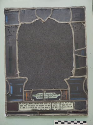
Because of the fragility of the disassembled panel, appropriate packaging to allow for safe transportation was needed. Packaging was made up in a layered system, with archival foam supporting and protecting fragile elements, such as gaps in the lead matrix (fig. 27) and the extracted central glass piece . The layered system has been taped together, allowing for elements of packaging to be reused again, once the panel has been fully conserved. Ideally this system should be transported within a suitably sized box, but it can also be carried on a flat surface over short distances.
Figure 27. Packaging for the lead matrix.
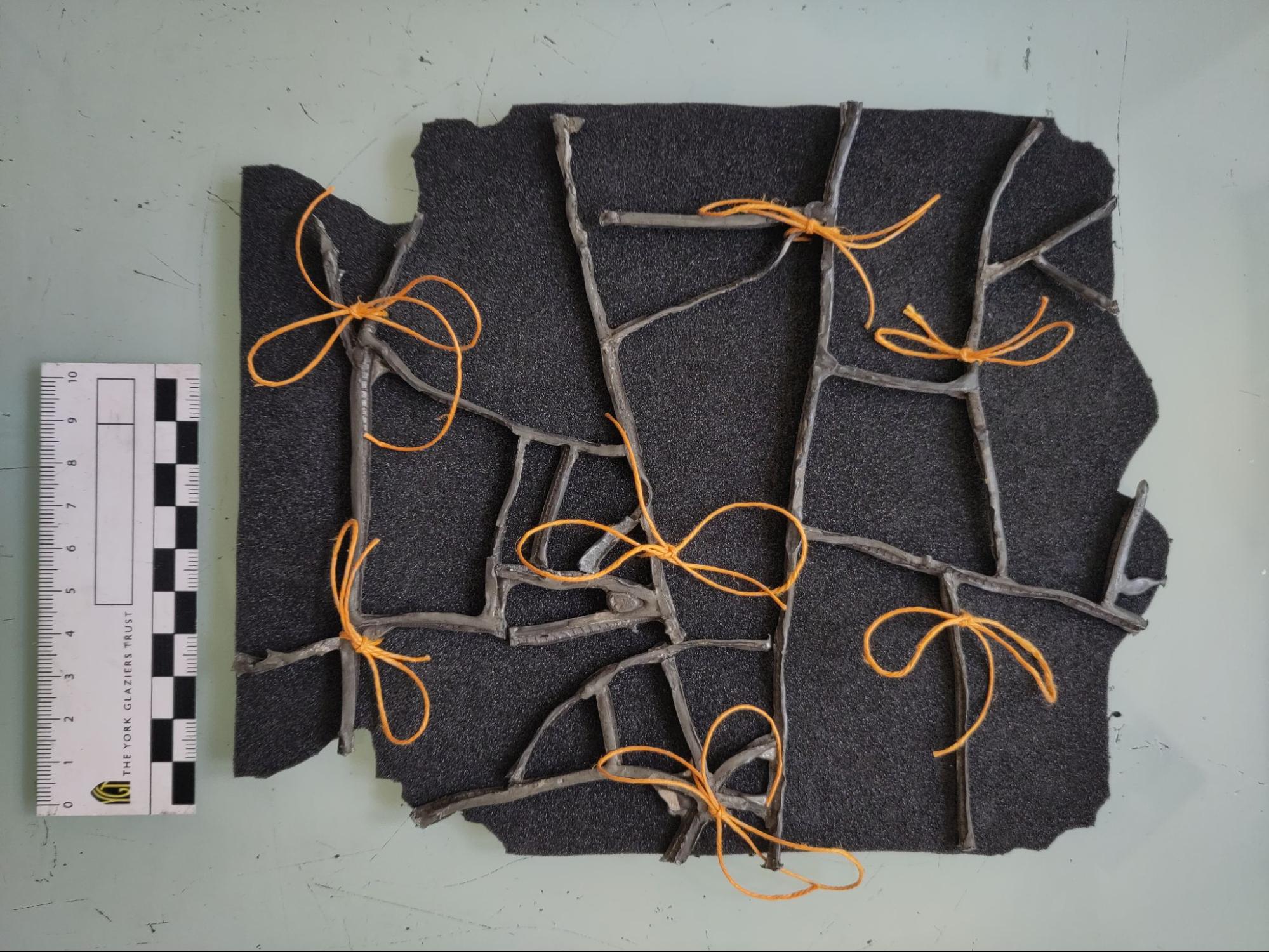
The removed mending lead matrix was tied to a foam cut out in the shape of the central glass piece, to give some indication of their original context (fig. 28). The foam gives the matrix some structure so that it can be transported, while being easily reversible if needed.
Figure 28. Packaging for mending lead matrix.
As the panel remains in a deconstructed state, it is particularly fragile and should be kept within the protective packaging, especially during travel. Special care should be taken with the thin extracted glass.
The panel has been treated with a UV sensitive adhesive and therefore should be stored in a dark environment going forwards.
I recommend that the gaps in the edge-bonded extracted glass be infilled to improve the stability of the panel, as well as its aesthetic value. Paraloid-B72 has been identified as a possible solution due to its reversible nature, but this has been difficult to implement in practice so other solutions should also be considered. Further suggestions for future conservation can be found in the treatment proposal.[15]
Date | Hours | Hours per day | |
24/04/2025 | 1h00 | Art historical research | 1 |
25/04/2025 | 2h00 | Panel photography | 2 |
27/04/2025 | 4h00 | Condition report and treatment proposal. | 4 |
29/04/2025 | 6h00 | Panel mapping and condition report | 6 |
5/05/2025 | 0h45 0h15 1h00 3h45 2h30 | Removing frame and initial clean with soft brush Setting up putty chemical tests Removing putty Removing glass pieces from figurative section Cleaning in-situ glass within lead matrix | 8.25 |
06/05/2025 | 5h00 4h00 | Cleaning glass within lead matrix Cleaning loose pieces of glass | 9 |
08/05/2025 | 4h45 0h15 4h00 | Cleaning loose pieces of glass Stabilising loose paint with Paraloid/acetone consolidant (7%) Stabilizing loose glass for edge-bonding (first round) | 9 |
09/05/2025 | 1h00 0h30 0h15 3h00 | Edge-bonding (loose glass, first round) Stabilizing in-situ glass for edge-bonding Edge-bonding in-situ glass Report writing | 4.75 |
10/05/2025 | 5h15 0h15 1h00 | Cleaning glass after edge-bonding Removing bad bond Stabilizing loose glass for edge-bonding (second round) | 6.5 |
12/05/2025 | 2h30 2h30 0h45 2h00 | Stabilizing loose glass for edge-bonding (second round) Paraloid infills test Edge-bonding loose glass (second round) | 8.75 |
13/05/2025 | 3h30 2h00 0h30 1h30 | Cleaning glass after edge-bonding (second round) Stabilizing loose glass for edge-bonding (third round) Edge-bonding (third round) Report writing | 7.5 |
14/05/2025 | 2h45 4h00 0h15 | Cleaning glass after edge-bonding (third round) Paraloid infills. Reapplying edge-bonding for weakened bond | 7 |
15/05/2025 | 2h00 1h00 2h00 | Paraloid infills Packaging Report writing | 5 |
16/05/2025 | 6h30 0h30 | Cleaning up paraloid infills Report writing | 7 |
17/05/2025 | 4h00 | Report writing | 4 |
19/05/2025 | 5h30 4h00 | Cold painting Report writing | 9.5 |
20/05/2025 | 2h00 4h00 | Photography Mapping interventions | 6 |
Total project time: 105.25 hours
[1] Pliny the Elder, Naturalis Historia, trans. John Bostock and Henry Riley (London: H. G. Bohn, 1855), Book 35.
[2] Oxford Dictionary of Proverbs, ed. Jennifer Speake (Oxford: Oxford University Press, 2015), s.v.
"Let the Cobbler stick to his last."
[3] James Hankins, Plato In the Italian Renaissance (Leiden: Brill, 1990), 1:4.
[4] Elisabeth Jägers, Hannelore Römich, Carola Müller-Weinitsche, “Konservierungsmaterialien und Methoden,” in Restaurierung und Konservierung historischer Glasmalereien, ed. A. Wolff, trans. Joseph Elders, Joseph Spooner, Sebastian Strobl (Mainz: Verlag Philipp von Zabern, 2000).
[5] Section 4, page 8.
[6] Section 4, page 9.
[7] See Appendix III.
[8] See Appendix III.
[9] Section 4, page 9.
[10] Ivo Rauch, “Konservierung und Restaurierung historischer Glasmalereien. Eine Einführung in die Problematik,” trans. Joseph Spooner. Die Denkmalpflege 62, no. 2, (2004): 141-50.
[11] Sasha Chapman and David Mason, “Literature Review: The Use of Paraloid B-72 as a Surface Consolidant for Stained Glass,” Journal of the American Institute for Conservation 42, no. 2 (2003): 386.
[12] Section 4, page 10.
[13] Section 4, page 1.
[14] Laura Chaillie, The Conservator's Cookbook: Solution Preparation for the Heritage Professional (Abingdon & New York: Routledge, 2025), 60.
[15] Section 4, page 11.